If you want to professionally develop for ANT+ you likely go out and buy this, an ANT+ development kit. It’s 412 dollars from Digikey here. Or maybe you do what I did and you just buy the actual modules and attempt to solder onto them… which is what I did in the picture below.

And the reverse side. Okay, so this was my second attempt, after my first attempt didn’t work at the time. The surface mount pads have small holes that perfectly fit the thin wires from resistors. Attempt one had me soldering these wires into the small holes – but I couldn’t get it to communicate – this was October 2011 .

An electrical engineer would probably be ashamed of what I’m doing, but I’m a mechanical who’s done most of my electrical learning on my own since I was a kid. This is further refined by my Masters being very much electro-mechanical in nature.
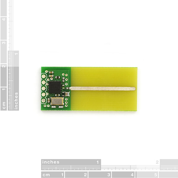
Since I couldn’t get these working and I was in the midst of trying to port my cycle training software to a .NETMF microcontroller and no longer had a way to talk to the speed/cadence or heart rate sensors I looked at the alternative I wanted to avoid (due to lack of certification) which was the Sparkfun ANT+ transciever.

Wired it up, programmed a C# library based off the C libraries and code for HRM that have been around the web, and moved on.
Fast forward to now. I’m building a power meter. Actually, version 3 of a power meter. The second was built and works, but isn’t nice to look at. See the wires going everywhere. The intermediary board for the analog front end (Instrumentation amp + 16bit ADC 100ksps) and that Sparkfun board trimmed and glued to the back of the Arduino Pro Micro board. So I’m committed to ANT+, and in fact I’ll go so far as to say attempting a power meter with any other protocol is likely a bad idea in my opinion. It’s standard and it works and it’s reliable.

So what about Version 3 – This is the circuit board I’ve been designing.

Notice how it’s designed to fit right inside the BB torque tube. See those five pins that haven’t been routed. They would go to the Sparkfun wireless transceiver board. However, if you clicked the link to this before you’ll see it’s discontinued. I noticed this last week. I had problems with the ANT OEM boards before, I spent weeks unable to get the microcontroller to talk to the board. I was at wits end until I switched to the Sparkfun board.

So I decided this week to attempt it again, and wire it into my “fake” power meter. That is to say my simulator prototype with my .NETMF board, the FEZ Panda II.
I didn’t believe it when it happened, but it worked the first time I wired it up without a modification. I had to check to make sure my V2 prototype wasn’t transmitting when I fired up the ANT+ display simulator. I’ll be switching to the new OEM AP2 module and redesigning my board again. I emailed Dynastream and they have a SoC coming for ANT+ applications. A32bit Cortex M0 + essentially an AP2 all in one chip. It’s called the nRF51422 and development kits will be available in September from distributors – EDIT:
What would be an even greater dream is if they released OEM modules like the ones I’m using with the nRF51422 with all the nice FCC, CE, etc certification and all I had to do was port my Powermeter to the Cortex M0 code and make board to mount it with the analog chips. Sadly the nRF51422 will only have 10 bit ADC’s which I’ll say are insufficient in resolution for a power meter. Though maybe if the gain was set very very carefully on an AD623 or similar. I’m using the AD623 + Vishay precision resistors to set gains of 200-300 which for my setup is necessary. Could potentially go to 500.
If anyone wants my C# ANT+ .NETMF library just drop me an email.

I like the way you soldered the AP2 module. I want to use this module in a little project of pairing with a Garmin device and send data to it, that I hope will then show up in the garmin recorded .fit file? I decided on the AP2 module like the one you used, but a version with a molex header, see here: http://www.thisisant.com/developer/components/ap2-modules/#77_tab
ReplyDeleteMy plan is to solder a molex receptacle (http://goo.gl/RXIx2j) onto a Schmartboard, like this one: http://goo.gl/vtVjLW
Then for development I want to interface with an Arduino, Initially I am planning to double this setup, one AP2 as master sending node, and another as a receiver, so I can work out in principle if I can make the protocol work. I realise I have to spend a bit more thinking about it, but thank you for this interesting post.
I've also found a good write-up here: http://jbremnant.wordpress.com/2011/11/27/ant-between-msp430-and-android/
Cheers
Martin
Sorry, here the links again:
Delete- Another blog using ANT module to send data
- Molex receptacle with 0.5mm pitch
- The Schmartboard to take surface mounted molex
- AP2 with different options