Wednesday, August 29, 2012

Omega Strain Gauges

Parts are starting to arrive for the V3 Power Meter. The first item to arrive in are the new shear strain gauges. I’ve never used Omega Strain Gauges, only Vishay at this point. Both companies have very similar claims in terms of tolerances for resistance and sensitivity, however on receipt of the gauges something is very noticeable. (I should be picking up some backordered strain gauges on Friday from the Vishay dealer here in Ontario. I’ve had several calls from the HBM rep for work. They don’t currently make any gauges suitable for my application though.)
DSC_8927
DSC_8932
What I immediately notice is that the Vishay packaging contains tested data from the batch.  You see the batch and foil is tracked, they provide thermal coefficients, and gauge factor and tolerances. Omega has gauge factor and Tolerance and batch data, but it’s not readily apparent what the tolerance is of (resistance or gauge factor). While I won’t be using the thermal coefficients I do believe that the Vishay is providing a greater amount of testing data which might give more confidence.

There is a big however; most of this data is relatively meaningless in terms of creating a load cell. The reason for this is relatively simple. The shear gauges are full bridge, so they are thermally compensated. My recent experience using strain gauges in research related to the Nuclear industry is that I’ve been able to get amazing accuracy out of half bridges. In some cases my results have been < 0.3% different from theoretical. During testing we found half bridges / full bridges were much more thermally stable than quarter bridge arrangements. For those who may need some background, check out Wikipedia on wheatstone bridges. So that takes care of the thermal coefficients.

The sensor is going to be calibrated against a known load and thus the gauge factor has little impact. The only factor of significance is the resistance tolerance with respect to each other gauge as this will affect any offsets present in the wheatstone bridge. My V2 setup uses a gain of 200 and a voltage of 3.3V supply. If for instance the wheatstone bridge has small mismatch of resistance causing a 0.5mv offset, this could become 0.1V after gain, or about 3% my entire voltage range. However since I’m only measuring torque in one direction this could potentially be 6% as I could lose have the available range if my reference is Vss/2.

On to the actual gauges.
DSC_8926
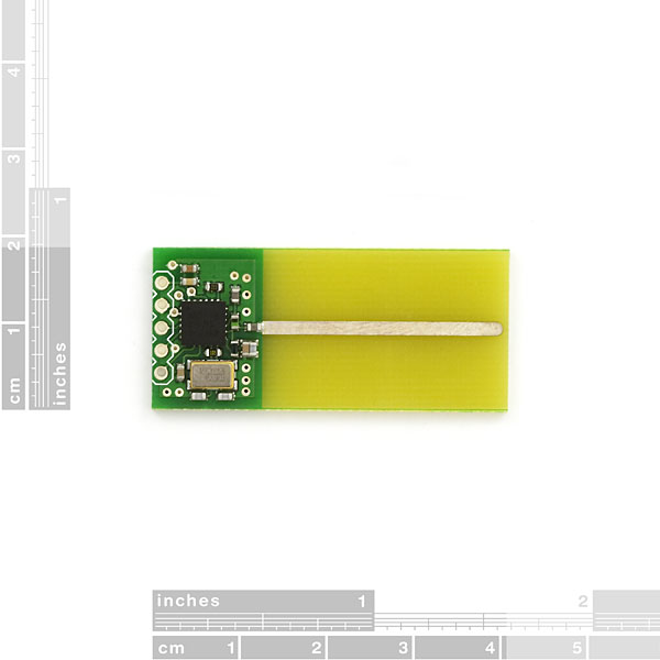
Small double shear gauge next to the 20 x 20 mm AP2 module.I think it’s about 8mm x 10mm. I was impressed by the quality of the grid. This is not even considering these gauges are about 10 dollars each, where the other single shear gauges I’ve used from Vishay is $35 each and the double bending bridge ones are about $22.

In order to make a power meter that measures each leg you will need two of these gauges. Total cost is about $20. Using my double bending bridge gauges you need 4 x 20 = $80. This would have a significant impact on cost.

For anyone who has read Hunter Allan’s Book he lists out how many gauges per power meter each has and it feels like it’s implying more gauges means more accurate. This is not the necessarily the case.
SRM and Quarq both need to use a decoupling algorithm. This means that the stiffness of the surrounding area affects how much each arm of the crank spider arm affects the torque. A professor at my university showed me how this works with a stuart gough load cell with 6 arms that only measure axial forces to determine torque and forces in all Cartesian directions.

The choice on how to instrument the crank determines how many gauges are used. Most commercial load cells are a single full bridge transducer. This is essentially my design as I do not require any decoupling algorithm. So in short my design will have 4 “gauges” on the one backing for each leg, totalling 8.

Sunday, August 26, 2012

Kurt Kinetic Power Meter

As promised in a previous post, here is the Kurt Kinetic Power Meter Mark I. Note, that the ANT+ key HAS BEEN REMOVED so you will need to re-insert it in the code or else it won’t pick it up. I haven’t integrated the coast down to measure the mass moment of inertia, but based on the provided regression on the Kurt Kinetic website. This week I’ll try and capture some data. I’ve read that the fluid trainers need to stabilize thermally before you can get a consistent reading so I’ll try and do a trainer work out and capture several coast downs from 35+ km/hr to about 0 and see if I can get the math to line up.

DSC_8921

Ignore the AP2 module and the msop breakout board – as seen in a previous post, that was for testing the AP2 module with my .net board.

For this, I’m using an Arduino Leonardo (Atmega 32U4) which is 5V, and the Sparkfun ANT+ module is 3.3V, so  I’m using a simple resistor voltage divider circuit on the leonardo’s Tx lines. The magnetic reed switch from a cheap Cateye cycle computer is used for magnetic pickup.The reed switch connects between 3.3 (or 5v) an the output side is connected to digital pin 3. A 1k resistor runs from pin 3 to gnd as a pulldown. This circuit works equally well with a pullup resistor instead. The Tx/Rx lines of the ANT+ board are wired to the Rx/Tx lines of the microcontroller.

DSC_8923

I couldn’t quite capture swiping a magnet in front of the reed switch and capture the power on the cycle computer, but i was able to take a screen capture. The code needs work, the power listed on the COM16 is accumulated. As I’ve found before in testing, swinging a magnet back and forth in front of these things is very inconsistent.

Kurt_kinetic

Below is the code

Cheers Winking smile


#define UCHAR unsigned char
#define MESG_TX_SYNC ((UCHAR)0xA4)
#define MESG_SYSTEM_RESET_ID ((UCHAR)0x4A)
#define MESG_NETWORK_KEY_ID ((UCHAR)0x46)
#define MESG_ASSIGN_CHANNEL_ID ((UCHAR)0x42)
#define MESG_CHANNEL_ID_ID ((UCHAR)0x51)
#define MESG_CHANNEL_RADIO_FREQ_ID ((UCHAR)0x45)
#define MESG_CHANNEL_MESG_PERIOD_ID ((UCHAR)0x43) // Set channel period 0x43
#define MESG_RADIO_TX_POWER_ID ((UCHAR)0x47) // Set Tx Power 0x47
#define MESG_CHANNEL_SEARCH_TIMEOUT_ID ((UCHAR)0x44) // Set Channel Search Timeout 0x44
#define MESG_OPEN_CHANNEL_ID ((UCHAR)0x4B) // ID Byte 0x4B
#define MESG_BROADCAST_DATA_ID ((UCHAR)0x4E)

const int Mag_pickup = 3; // the number of the pushbutton pin
int pin = 13;
volatile int state = LOW;
unsigned long time1;
unsigned long time2;
unsigned long period;

double omega;
double velocity;
byte ANT_event = 0;
uint16_t ANT_INST_power = 0;
uint16_t ANT_power = 0;
double powerconst;

boolean recalc = 0;

long lastDebounceTime = 0; // the last time the output pin was toggled
long debounceDelay = 10; // the debounce time; increase if the output flickers
int buttonState; // the current reading from the input pin
int lastButtonState = LOW; // the previous reading from the input pin
boolean sent = 0;

void setup()
{
Serial1.begin(4800);
Serial.begin(115200);
pinMode(pin, OUTPUT);
//attachInterrupt(0, blink, RISING);
delay(5000);
Serial1.flush();
delay(50);
initiate();
delay(20);
}

void loop()
{

Crank_Pickup();

if (recalc == 1)
{
ANT_event++;
period = time1 - time2;
omega = 6283185.3072/period;
velocity = double(2096000)/double(period);
ANT_INST_power = uint16_t(11.73235736*velocity+0.220287158*velocity*velocity*velocity);
ANT_power += ANT_INST_power;
Serial.print("period: ");
Serial.print(period);
Serial.print("omega: ");
Serial.print(omega);
Serial.print("Vel: ");
Serial.print(velocity);
Serial.print(" Power: ");
Serial.println(ANT_power);
basicpower();
Serial1.flush();
recalc = 0;
}


}

void Crank_Pickup()
{
int reading = digitalRead(Mag_pickup);
if (reading != lastButtonState) {
// reset the debouncing timer
lastDebounceTime = millis();
sent = 0;
}

if ((millis() - lastDebounceTime) > debounceDelay) {
buttonState = reading;
if (buttonState == 1)
{
if (sent == 0)
{
sent = 1;
blink();
}
}
}
lastButtonState = reading;
}

void blink()
{
recalc = 1;
state = !state;
time2 = time1;
time1 = micros();
}

UCHAR checkSum(UCHAR *data, int length)
{
int i;
UCHAR chksum = data[0];
for (i = 1; i < length; i++)
chksum ^= data[i]; // +1 since skip prefix sync code, we already counted it
return chksum;
}

void reset ()
{
uint8_t buf[5];
buf[0] = MESG_TX_SYNC; // SYNC Byte
buf[1] = 0x01; // LENGTH Byte
buf[2] = MESG_SYSTEM_RESET_ID; // ID Byte
buf[3] = 0x00; // Data Byte N (N=LENGTH)
buf[4] = checkSum(buf,4);
ANTsend(buf,5);
}


void SetNetwork() //thisisANT.com and become an ANT+ Adopter
{
uint8_t buf[13];
buf[0] = MESG_TX_SYNC; // SYNC Byte
buf[1] = 0x09; // LENGTH Byte
buf[2] = MESG_NETWORK_KEY_ID; // ID Byte
buf[3] = 0x00; // Data Byte N (
buf[4] = 0x00; // Data Byte N (N=LENGTH)
buf[5] = 0x00; // Data Byte N (N=LENGTH)
buf[6] = 0x00; // Data Byte N (N=LENGTH)
buf[7] = 0x00; // Data Byte N (N=LENGTH)
buf[8] = 0x00; // Data Byte N (N=LENGTH)
buf[9] = 0x00; // Data Byte N (N=LENGTH)
buf[10] = 0x00; // Data Byte N (N=LENGTH)
buf[11] = 0x00; // Data Byte N (N=LENGTH)
buf[12] = checkSum(buf, 12);
ANTsend(buf,13);
}
void assignch()
{
uint8_t buf[7];
buf[0] = MESG_TX_SYNC; // SYNC Byte
buf[1] = 0x03; // LENGTH Byte
buf[2] = MESG_ASSIGN_CHANNEL_ID; // ID Byte
buf[3] = 0x00; // Channel Number
buf[4] = 0x10; // Channel Type
buf[5] = 0x00; // Network ID
buf[6] = checkSum(buf,6);
ANTsend(buf,7);
}

void SetChID()
{
uint8_t buf[9];
buf[0] = MESG_TX_SYNC; // SYNC Byte
buf[1] = 0x05; // LENGTH Byte
buf[2] = MESG_CHANNEL_ID_ID; // Assign Channel ID 0x51
buf[3] = 0x00; // channel number
buf[4] = 0x05; // Device number
buf[5] = 0x00; // Device number
buf[6] = 0x0B; //Device type ID
buf[7] = 0x00; //Transmission type -CHANGED
buf[8] = checkSum(buf, 8);
ANTsend(buf,9);
}

void ANTsend(uint8_t buf[], int length){
//Serial.print("ANTsend TX: ");
for(int i = 0 ; i <= length ; i++)
{
//Serial.print(buf[i], HEX);
//Serial.print(" ");
Serial1.write(buf[i]);
}
//Serial.println("");
}
void SetFreq()
{
uint8_t buf[6];
buf[0] = MESG_TX_SYNC; // SYNC Byte
buf[1] = 0x02; // LENGTH Byte
buf[2] = MESG_CHANNEL_RADIO_FREQ_ID; // Set Channel RF Freq 0x45
buf[3] = 0x00; // Channel number
buf[4] = 0x39; // Frequency
buf[5] = checkSum(buf, 5);
ANTsend(buf,6);
}

void SetPeriod()
{
uint8_t buf[7];
buf[0] = MESG_TX_SYNC; // SYNC Byte
buf[1] = 0x03; // LENGTH Byte
buf[2] = MESG_CHANNEL_MESG_PERIOD_ID; // Set channel period 0x43
buf[3] = 0x00; // Channel number
buf[4] = 0xF6; // Messaging Period byte1
buf[5] = 0x1f; // Messaging period byte2
buf[6] = checkSum(buf, 6);
ANTsend(buf,7);
}

void SetPower()
{
uint8_t buf[6];
buf[0] = MESG_TX_SYNC; // SYNC Byte
buf[1] = 0x02; // LENGTH Byte
buf[2] = MESG_RADIO_TX_POWER_ID; // Set Tx Power 0x47
buf[3] = 0x00; // Channel Number
buf[4] = 0x03; // Tx power
buf[5] = checkSum(buf, 5);
ANTsend(buf,6);
}

void SetTimeout()
{
uint8_t buf[6];
buf[0] = MESG_TX_SYNC; // SYNC Byte
buf[1] = 0x02; // LENGTH Byte
buf[2] = MESG_CHANNEL_SEARCH_TIMEOUT_ID; // Set Channel Search Timeout 0x44
buf[3] = 0x00; // Channel number
buf[4] = 0x1E; // Set timeout
buf[5] = checkSum(buf, 5);
ANTsend(buf,6);
}

void OpenChannel()
{
uint8_t buf[5];
buf[0] = MESG_TX_SYNC; // SYNC Byte
buf[1] = 0x01; // LENGTH Byte
buf[2] = MESG_OPEN_CHANNEL_ID; // ID Byte 0x4B
buf[3] = 0x00;
buf[4] = checkSum(buf, 4);
ANTsend(buf,5);
}

void initiate()
{
SetNetwork();
delay(100);
assignch();
delay(100);
SetChID();
delay(100);
SetFreq();
delay(100);
SetPeriod();
delay(100);
SetPower();
delay(100);
SetTimeout();
delay(100);
OpenChannel();
delay(100);

}

void basicpower()
{
uint8_t buf[13];
buf[0] = MESG_TX_SYNC; // SYNC Byte
buf[1] = 0x09; // LENGTH Byte
buf[2] = MESG_BROADCAST_DATA_ID; // 0x4E
buf[3] = 0x00; // Channel number
buf[4] = 0x10; // Basic power page identifier
buf[5] = ANT_event; // Event count
buf[6] = 0xFF; // Power differential
buf[7] = 0xFF; // Instant Cadence
buf[8] = byte(ANT_power & 0xFF); // Accumulated power LSB
buf[9] = byte((ANT_power >> 8) & 0xFF); // Accumulated power MSB
buf[10] = byte(ANT_INST_power & 0xFF);; // Instant power LSB
buf[11] = byte((ANT_INST_power >> 8) & 0xFF); // Instant power MSB
buf[12] = checkSum(buf, 12);
ANTsend(buf, 13);
}

Wednesday, August 22, 2012

AP2 Module and Design Changes

I’ve decided to migrate to the AP2 module for V3 as previously alluded to. So that means I need to mount the AP2 module via connector or soldering to the new board. I initially choose soldering because as seen below the AP2 module just barely fits inside the BB torque tube.DSC_8919

So I designed up the surface mount connector for the PCB according to the AP2 module datasheet. It ends up being a little bit bigger than the module. It ends up being 22mm wide, while the BB torque tube measures 21.27mm. It just barely won’t fit as seen by my paper print off cut to scale.

image

Look at that bowing of just a piece of paper. I could trim it back, and I’m not sure how close the PCB places will allow me to be to the edge. Can I have copper right to the edge of the board? I’ll find this out shortly.

DSC_8920

However I’ve been thinking about my V2 design. The trace antenna inside that torque tube is really doing a number on garbling my data causing a lot of failed signals. I’ve ordered new gauges, this time from Omega. Honestly, I prefer Vishay. I was at their facility, I got to see around and talk to applications engineers, and learn some “secrets” to a good strain gauge setup. However they don’t make a double shear gauge as small as I want and I’m not yet willing to pay the setup and production fee for a new design.

I’m working on alternative placements for the microcontroller and transceiver board. I’m still planning a shear gauge inside the BB torque tube so I figure it might be wise to place the board near the other gauges. Namely mounting it to the back of the right crank arm or between the the crank spider arms next to the crank arm.

The V2 Prototype is based on an SRAM Rival crank before they switch to a hollow forged. The new one on Order, like shown in the last post which is on my current bike, is the newer hollow forged. These have a flat back which would be ideal for mounting on.

While I wait for new parts, I am planning to take a stab at another project. Making a pseudo power meter for cycle trainers based on a combination of the regression curved for power dissipation combined with the flywheel mass used to calculated the additional force due to acceleration.

P = C1 * V + C2 *V^2 + C3*V^3 + (m_o * alpha)*omega

Where C1 – C3 is the regressed curve constants, V is rotational velocity, m_o is the polar moment of inertia, alpha is rotational acceleration in rad/s^2 ( m_o * alpha = Torque in N-M), and omega is mean rotational velocity during that acceleration period in rad/s.

The tricky part is getting m_o. Two methods – Calculated it based on size and weights or materials for the flywheel and roller and guess the wheel, or try and figure out how to calculate it based on a coast down time from a given speed.

What will be needed is a microcontroller, an ANT+ transceiver and a magnet pickup and magnet. I’m curious if the Garmin speed cadence sensors are using an MSP430. They could potentially be hacked and reprogrammed to do this. With so much stuff on order I’m not quite willing to buy another ANT+ device only to intentionally rip it open with no hope of getting it back together so this will be DIY with my existing stuff.

Monday, August 20, 2012

SoC Distributors and Some Minor Edits

I'm starting to get some new traffic and I really appreciate it. Again, feel free to email me or post comments. I'm eager to hear people's feedback -- I suspect people are waiting to see the progress on V3 or at least a video of V2 working. I promise I'm working on both.

Some things to clarify.

I mistakenly presumed that Digikey is a distributor for Nordic's new SoC ANT+ chip, the nRF51422. That is not the case, they are only a distributor for some of the ANT+ products and not Nordic. Nordics offical list of distributors for Canada can be found here http://www.nordicsemi.com/eng/distributor/country/39.

If you want to become an ANT+ adopter you can do so here. It  will give you access to the device profiles, the network key, example codes, and more. It will also allow you to upgrade to an ANT+ Alliance member in the future -- I suspect I'll be doing this in the future as I'm working on a peddle stroke analysis which would be done on the power meter and offloaded on a secondary channel or with a revised profile.

The reason I mention this is because the ANT+ Network key is proprietary. ANT+ gives us an interoperable connection between sensors and watches, cycle computers and more but a big part of this is maintaining conformance. That is why they exist and they are key to the industry success. So anything I post will not contain the network key as this would breech the ANT+ Adopter agreement. Keep this in mind if you plan to release your own code as well.

Friday, August 17, 2012

ANT+ for embedded

Have you ever been use to using a piece of hardware, or software, and then turn around to order new parts only to find that they are deprecated, unavailable, or have just gone the way of the tumbleweed. Well that is where I was this week when it came to ANT+ transceiver boards.
If you want to professionally develop for ANT+ you likely go out and buy this, an ANT+ development kit. It’s 412 dollars from Digikey here. Or maybe you do what I did and you just buy the actual modules and attempt to solder onto them… which is what I did in the picture below.
DSC_8914
And the reverse side. Okay, so this was my second attempt, after my first attempt didn’t work at the time. The surface mount pads have small holes that perfectly fit the thin wires from resistors. Attempt one had me soldering these wires into the small holes – but I couldn’t get it to communicate – this was October 2011 . DSC_8913
An electrical engineer would probably be ashamed of what I’m doing, but I’m a mechanical who’s done most of my electrical learning on my own since I was a kid. This is further refined by my Masters being very much electro-mechanical in nature.
Since I couldn’t get these working and I was in the midst of trying to port my cycle training software to a .NETMF microcontroller and no longer had a way to talk to the speed/cadence or heart rate sensors I looked at the alternative I wanted to avoid (due to lack of certification) which was the Sparkfun ANT+ transciever.

Wired it up, programmed a C# library based off the C libraries and code for HRM that have been around the web, and moved on.
Fast forward to now. I’m building a power meter. Actually, version 3 of a power meter. The second was built and works, but isn’t nice to look at. See the wires going everywhere. The intermediary board for the analog front end (Instrumentation amp + 16bit ADC 100ksps) and that Sparkfun board trimmed and glued to the back of the Arduino Pro Micro board. So I’m committed to ANT+, and in fact I’ll go so far as to say attempting a power meter with any other protocol is likely a bad idea in my opinion. It’s standard and it works and it’s reliable.
DSC_8912
So what about Version 3 – This is the circuit board I’ve been designing.
image
Notice how it’s designed to fit right inside the BB torque tube. See those five pins that haven’t been routed. They would go to the Sparkfun wireless transceiver board. However, if you clicked the link to this before you’ll see it’s discontinued. I noticed this last week. I had problems with the ANT OEM boards before, I spent weeks unable to get the microcontroller to talk to the board. I was at wits end until I switched to the Sparkfun board.
DSC_8907
So I decided this week to attempt it again, and wire it into my “fake” power meter. That is to say my simulator prototype with my .NETMF board, the FEZ Panda II.
I didn’t believe it when it happened, but it worked the first time I wired it up without a modification. I had to check to make sure my V2 prototype wasn’t transmitting when I fired up the ANT+ display simulator. I’ll be switching to the new OEM AP2 module and redesigning my board again. I emailed Dynastream and they have a SoC coming for ANT+ applications. A32bit Cortex M0 + essentially an AP2 all in one chip. It’s called the nRF51422 and development kits will be available in September from distributors – EDIT: which I take to mean Digikey. Digikey not not a Nordic Distributor, my mistake. Sorry about the confusion. I still like the concept of eliminating my two chip setup.

What would be an even greater dream is if they released OEM modules like the ones I’m using with the nRF51422 with all the nice FCC, CE, etc certification and all I had to do was port my Powermeter to the Cortex M0 code and make board to mount it with the analog chips. Sadly the nRF51422 will only have 10 bit ADC’s which I’ll say are insufficient in resolution for a power meter. Though maybe if the gain was set very very carefully on an AD623 or similar. I’m using the AD623 + Vishay precision resistors to set gains of 200-300 which for my setup is necessary. Could potentially go to 500.
If anyone wants my C# ANT+ .NETMF library just drop me an email.
DSC_8916

Sunday, August 12, 2012

Power Meter V2

Power meters are essentially a combination of torque and cadence. Torque  (N-M) times angular velocity (rad/s) = power (watts). Cyclists generally know about their cadence through a magnet on the crank and a pickup on the bike measuring the time and calculating RPM.

However, what about torque? This is a more painful proposition to measure and as such several companies have come out with devices to do this. The first and “golden” standard is SRM. I honestly don’t see any engineering superiority but they have the experience of being the first. SRM has four small cantilever beams as a crank spider (instead of the normal 5) measuring strain at each beam and converting it to torque between the BB and the chain ring. They have an outer ring which provides sufficient stiffness that changing chain rings shouldn’t require calibration.

Quarq on the other hand doesn’t have this stiffening ring. What does that mean? Well, each set of chain rings have a different stiffness – which is how much they deflect in a rotational direction for a given load. Since the torque will always be transferred mostly by the spider arm nearest the top off the chain ring, how stiff the chain ring is affects how much the next arms are transferring. This is why they have calibration tables or have to be sent back for calibration.

Powertap is a simple torque tube. Simple, reliable, and generally lower cost.

Coming soon is Garmin’s vector product, but it’s been delayed several times. It’s claim to fame is left and right power readings – as a result they updated the Garmin EDGE 500 to show this.

What is my prototype then?

Left and Right power, but measure them in the crank. How. Well Prototype V2 shown below has strain gauges at the crank arms measuring torque directly. This allows measuring the left and right legs individually. Prototype V3 which be slightly different.

V2 works, but has some issues. I’ll be posting a video in the next couple of weeks hopefully. It’s a bit of a pain as the left arm has to be soldered on after the crank is installed as wires run through the BB hollow shaft. This will NOT be the case for V3 as the left leg will be measured as torque through this shaft and not at the arm. This idea was actually presented to Quarq in a job application. Hey look, public reveal thus non-patentable!

DSC_8869

The Power Meter Origin

Once upon a time during my Master’s degree I was exposed to building a load cell. It was a very very small load cell. In reality this was just an exercise in strain gauging that didn’t go anywhere for the degree. It did give me some exposure to something interesting and useful. In fact, as a direct result of this my current company sent me away for professional training to ensure my skills were sufficient for a testing program.

I’m going to give the abbreviated version of this unfinished website.

This is what I’ve been referring to as V1. It proved a concept, but at the time my electrical experience with strain gauging wasn’t sufficient to see the problems. Mainly the prototyping board and loose wires plus the high gain give very noisy results. The cheap completion resistors don’t help either. Vishay has a training course that is 3 days long and about 1200 dollars. If you are serious about strain gauging I suggest you do it or get an experience person to run you through the basics of everything with a test piece or 3.

Strain Gauges from Vishay. General purpose gauges with a protective cover on the gauge face.

The FSA crank which I will be instrumenting

The Arduino and bridge completion resistors. *Don’t use these cheap resistors for bridge completion. Your project will be a failure… why? Drift. These resistors have 300-500ppm/degree drift. What you want is wirewound or preferably thin film. Vishay make them. They are around 5 to 15 dollars each. My V3 design will eliminate most of these costly resistors, the first step to eliminating them is a full bridge strain circuit. Most sensitive and can be lower cost – sometimes.

Tiny Axial load cell with poor soldering directly to the gauge from my Masters program.

Sanding time. Need to get down to the bare metal and prep the surface for the gauge application.

Okay bare metal time, sanding in stages

120 grit go!

Progressively sand. 320 grit then 600. There is no need to go beyond this. If you polish the surface the glue won’t have much to adhere to, but you don’t want it too lumpy or the glue line will be inconsistent.

Wipe clean and apply the gauge by laying it out on a clean piece of glass or plastic and picking it up with the tape. Place it down in the area which you want to apply (normally you would have alignment marks, but since it would be calibrated after the fact for torque and not surface strain, alignment isn’t critical).

Pull the tape back, apply the glue to the surface and press the gauge forward ensuring no air bubbles. Hold with thumb pressure for at least 1 minute. Check out Vishay Micromeasurements site for more instructions.

Solder on fine wires, usually 30 – 36 AWG wires to the pads. You’ll see my new version using bondable terminals as it’s easier to bond small wires to gauges and big wires to the terminals. It also provides strain relief.

121 Ohms which is about right.

121 ohms, good

Trying to apply load and take a picture after the two gauges are wired in series and measured against the mid point of a voltage divider creating a half wheatstone bridge arrangement.

Well, I don't want to break the gages so lets protect them. Epoxy, 5 min kind. Very flexible and soft compared to metal and the superglue glueline.


After mixing coat the gauges. Let set. This 5 minute stuff takes several hours to fully cure but is mostly cured in 5 – 20 minutes.

Sunday, August 5, 2012

Vostro V13 USB SSD Hack

As a mechanical engineer I tend to need Windows software, especially during the days of my masters degree, which is when I actually did this hack. I did however want to try Ubuntu. So what’s my options, partition off the drive and – wait a minute, that seems like a terrible idea when I’m in the middle of a degree and all my work is on that drive.

DSC_8656

So I went to ebay and got a mini pci-e to USB adapter and NCIX and got a Cosair Voyager GTR 32GB usb memory stick.

For anyone who doesn’t know, the Dell Vostro V13 was based on Adamo, and as a result is 1) super cheap 2) poorly built and 3) thinner than the original Macbook Air (well, the air is wedge shaped, this is not, so the v13 is thinner than the original Air’s thick end). So you can guess it’s cram packed inside. All is not lost, near the centre there is a slot for a full length mini pci-e card.

DSC_8661

So here is the adapter, wired up to the adapter board. You’ll notice that there is a wire coming off the board. Mini-PCI-E does not have a 5V line to power the USB device, so an additional wire needs to run to a 5V source.

DSC_8662

I had to break off the little connectors on the back and solder directly to the board in order to make it fit. I also shaved down the ends near the card edge connector as seen by the tapered angle. They didn’t have the right around of clearance.

Another view.

DSC_8664

Another view.

DSC_8665

So put that in the connector. I found the easiest place to get 5V was from the hard drive. There is a giant resistor in line with the 5V line to the hard drive, I assume this is a current limiting resistor. I soldered on and ran the thin wire back.

DSC_8667

You can see the installed picture. The memory stick is on an angle. Several times I’ve removed and replace this as something like that on an angle is sure to alert airport security that something is amiss. I’ll fly domestic with it in, but I’ve pulled it for international flights. Wires and things on an angle might set someone off – then again, with all the peculiar shapes in new computers I might be just paranoid.

DSC_8668

If you do have a V13 you will probably have a problem where someday your computer doesn’t start and Dell refuses to admit a design problem. The plastic edge by the card slot pinches the white ribbon cable shown above right at the SATA TX and RX lines and causes a break. Computer can’t detect the hard drive then. Mine has broken twice – the first one month out of warranty…. which is great because dell had the laptop for another reason, refusing to repair… for 1.5 months and refused to extend my warranty that time period. My cousin’s V13 cable broke 3 times, twice under warranty, once not. Shaving this away has kept the laptop working without problem.

DSC_8669

Close it up!

DSC_8672

Boot it up!

DSC_8673

F12 and now you can see the USB drive has a ‘+’' by it!

DSC_8674

I had already installed Ubuntu onto the stick, but now you can just boot on in. GRUB is on the USB stick, but detected Windows on the other drive, but the hard drive won’t see the GRUB bootloader which is what I want.

DSC_8675

Success!

DSC_8678