This is broken down into a low volume startup company, and an even lower volume at home company.
Breakdown is that both end up with products around $750. More after the break
This is broken down into a low volume startup company, and an even lower volume at home company.
Breakdown is that both end up with products around $750. More after the break
Shipped! They were very quick at turning around the depanelizing of the other 92 orders and getting these in the post.
Obviously nothing huge in terms of news until I get these and try to reflow but I’m still here.
In other news DCrainmaker has an update on the stages powermeter. It seems they’ve dialled it in a bit. Honestly, while I think it’s as good in terms of accuracy it seems it’s holding up very well to scrutiny by several seasoned riders of the meter. For two stain gauge pairs and what I’ve proven to be 30 dollars of circuit boards on what I estimate to be a 30 dollar crank arm (I’ve sourced SRAM Rival’s for approximately $100 CAD + shipping) so these are 600 dollars for R&D / lights on / profit. In my world profit is really just R&D money.
This leads me to make comment on what I’ve seen in the industry in terms of pricing. While powermeters are getting more popular, all one has to do is spend 10 minutes searching craigslist / kijiji / etc to find that locally they are rare. So rare that I’ve seen someone in Alberta want 1500 for the SPIDER from a Quarq S975. Locally in Ontario it’s only recently that I’ve seen up to 4 Quarq units available and 2 - 3 SRM.
While looking for a test unit I spent some time and eventually got one reasonably priced which I plan on selling come Sept. These aren’t high volume products currently. This leads me to potential pricing structures, motivated by a person who emailed me asking me straight out “why do I [you] think power meters are so expensive”. I paused, and it felt like an epiphany. It’s not the parts, it’s the people!
I plan on posting soon about what it really costs, based on what I’ve learned today, to build and Sell a powermeter, and not take a loss. It’s harder than one thinks and I’m sure not everyone who were successful on being funded on Kickstarter or Indigogo have thought on this. I’ve read about a few who had no idea how to scale production from tens to hundreds, and were bunt (sometimes repeatedly) on the way. This has been the reason why you aren’t allowed to just show a 3D rendering of a product anymore for Kickstarter. Too many people who haven’t deliver or were months to over a year away.
Stay tuned and look forward to my post this week going to be called, “Good, Cheap, and Fast – Pick two”
Finally! 2 days ahead of schedule, now OSH Park needs to ship them. With any luck I’ll be attempting to reflow the boards late next week, early July.
Wow, how the time flies. Behind schedule on the enclosure design. Unlike the circuit board, 3D solid modelling is something I’ve been doing since high school. It’s what I’m classically trained to do. I think it’s valuable to take a mental break, though I’m not very good at it.
Seems like the $13 Freescale Freedom K25 board can be used as a programmer (CMSIS-DAP) style. This is great news. It’s essentially the cheapest ARM Cortex M0/1/2/3/4 programmer you can possibly get.
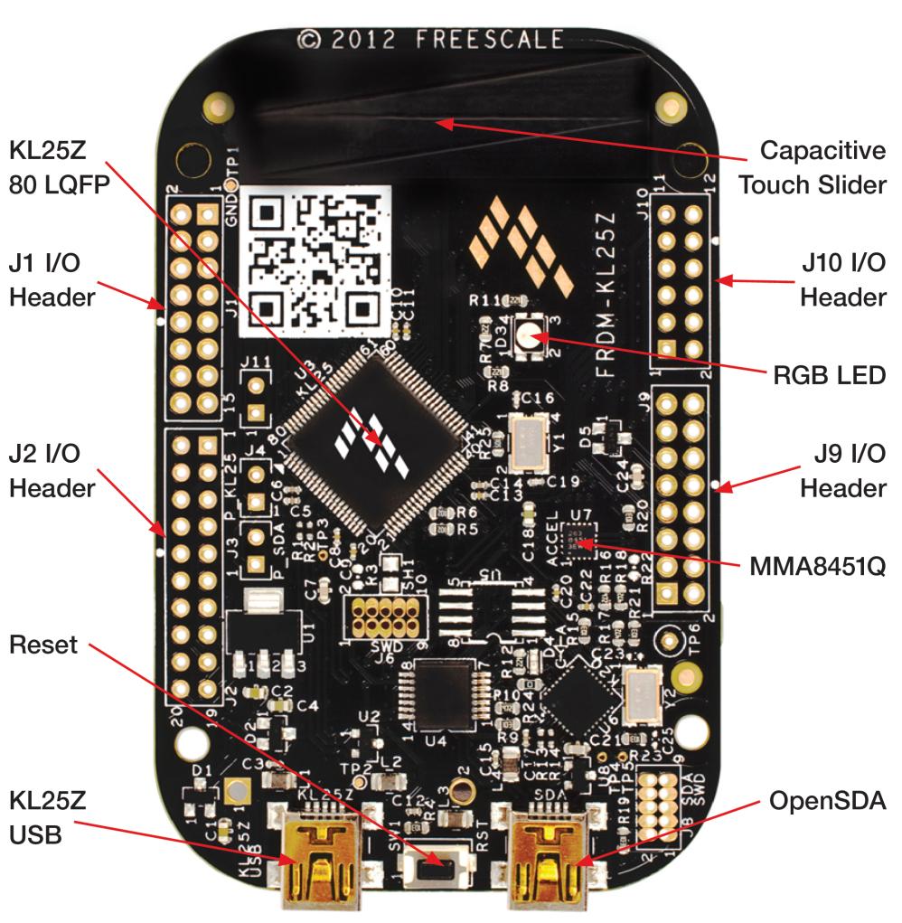
See the J6 header, if you cut a trace and install a header in one of the two pin slots you can use the small OpenSDA as a programmer for external boards. The J8 header is for programming the Arm Cortex at U6. So this board has two microcontrollers. One as a programmer, and the one you are meant to program. Pretty cool for $13 dollars. ARM Cortex is going to be huge for the microcontroller game as it develops maturity.
I’ve been testing my reflow oven setup and I’m having mixed feelings on using this specific toaster oven. Essentially it maxes out at 1 deg / sec but it can go a little faster if you “pre-heat” the oven. What this comes down to is that a cold oven has to heat up the metal and glass. If you pre-heat those things they will lose heat to the inside and the outside of the oven. This doesn’t help at high temps but at low temps it can allow it to match the curve better. I am concerned about the final heating to melting. I am afraid that it will take to long to heat up and therefore damage the FR-4 board. I’ve seen people do some real damage, scorching them for instance.
As you can see, doing this allows it to follow the intended curve more closely. This is at the limits of the generic lead reflow curve though.
While I ordered the circuit boards (6) from OSHpark, I needed a reflow stencil. This unexpectedly arrived very early compared to when I thought it would arrive. I chose Pololu’s slowest service, 5 day turn around. Shipping to Canada was about as expensive as the stencil, but was next day I think and I never chose the highest shipping available.
Below you can see the stencil. The QFN and peculiar Balun look like they are on the verge of not being usable, though I have no idea or experience. This has more to do with the limitations of laser cut out mylar I think. There was no bridging on the QFN cutouts. I don’t suspect I’ll have a problem with their work. I tried the Balun out to compare as it’s a non-standard layout. It is so small. I am having concerns about it and the 0402 components. If this backfires I’ll redo it with 0805 and a component based Balun. This means the board will get a little bigger but means that only the QFN would have to be reflowed.
During the weekend I attended the Guelph One Triathlon (as a spectator, due to my terrible swimming – if I don’t practice consistently I can’t make it around without drowning a couple of times). I did an unscientific survey of powermeters. Total count: Four. Three were Power2Max and one was Quarq. I was blown away.
I didn’t think many people would be running Power2Max in North America, let alone for it to be more common than Quarq or SRM. This was only the sprint distance, I didn’t attend the Olympic distance and suspect I would have seen more powermeters. When I’m closer to the Beta test group units I may start hanging out at Tri’s with a Booth to let people demo my device. However, this all leads me to feel more confident that there is market room for a $700 dollar unit that includes a crank – and not just a single arm that fakes the other side.
Firstly I want to give a huge thanks to Paul Archer. In my day job my employer has signs everywhere that say “Verify your design inputs”, and to that end we have a process of independent verification for everything. Paul has been that sounding board and verifier in the last couple of weeks, and without him I could have spent a lot more time dealing with issues of this board. I won’t say it’s perfect but it should work well.
I’m using a Texas instruments reference design for an PIFA style antenna that’s been extended. I plan to tune it with a 2.4GHz spectrum analyser by measuring power output. I’ve seen this technique several times.
I’ve realized today while checking footprints that very small components will have a “drop factor”. Essentially, 0402 parts and the BAL-nRF1D03 components will be hard to hold and align. So much so that I suspect that I will need a 3:1 ratio. Drop 2 – 3 and get one installed.
I do like the Purple boards. I’ll likely do a trace antenna design this week and also have it made in case the PIFA doesn’t work out. I am having trouble though making sure that I have the correct impedance match for a trace. Seems 1.6mm FR4 would require 2.81mm wide trace in 1oz copper according to the calculators, but most designs I’ve seen are much narrower. I’m not 100% sure who to trust. Antenna’s still feel like black magic thus far.
There is a 10 pin expansion header with 7 GPIO outputs that can be configured to any type of communications bus in addition to the 10 pin SWD programmer header. It has built in RTD sensor inputs for never having to zero your power meter. An RTD is a temperature sensor, and this will be used to measure each strain gauge setup. This is similar to Rotor Power. This won’t be fully implemented initially as it’ll require calibration for every power meter and I will have to sort that process but it will be.
Circuit Board design with the exception of the antenna and all respective parts (except the nRF51422 which I already have in my possession) have been ordered. They should arrive Tuesday or Wednesday which will allow me to check to make sure all the parts fit the pads I’ve outlined on the board and make any needed edits. During this time I’ll design the antenna.
Currently the board is 26mm x 32mm. It might have to get wider to accommodate the antenna slightly as I do no wish to use a meander trace. I want either a trace antenna or an IFA. I might make separate board with a ceramic antenna.
I’ve been given the suggestion to include an SMP connection such that a network analyser could be used to tune the antenna. I am going to try the technique where you make the antenna too long and cut it back. I’ve read about people tuning with a basic RF spectrum analyser with this method which is cheaper for me. (RF spectrum = 200 dollars, network analyser = thousands).
I need to spend some time on the silk screen labelling. It’d be an amateur mistake not to spend more time on this as it really helps clarify what the parts are for future debugging.
Total cost of all associated parts is somewhere in the vicinity of 30 – 40 dollars. However, I’ve been quoted at prototype assembly at 70 – 90 dollars a board. More motivation to finish the reflow toaster.


