Saturday, December 29, 2012

V3–Maybe it will work

image

Okay, so if you look at the Arduino code in the image you’ll see a commented out delay(3); I had put this in the wrong location. Because I’m not properly reading the RTS line I put in the delay, and it cleared up ANT+ communications. However it’s in the wrong location and now it’s a delay after every read! Stupid I know!

More after the break. Also I’m starting to use breaks on the blog so the amount of posting will be short. Just click the read more if you visit the main page.

Bluetooth (2.0) to ANT+ Bridge

So a little while ago I mentioned that it should be a very simple affair to connect the AP2 module to a Bluetooth SPP (Serial Port Protocol) transceiver. With everything working on 2.4Ghz this might be a wireless mess, but there should be lots of wireless space in the 2.4Ghz spectrum, suffice to say as long as several people are not using ANT+ and Bluetooth in the same area.

Why bridge things?

Well, it’s simple. Most phones don’t have ANT+ and it’s the #1 question I’m asked about the power meter combined with BTLE on Android, the dominate phone OS, does not have BTLE sorted out in the slightest. I don’t claim to know much about BTLE and it’s problems on Android but the group on Linkedin makes it clear that it’s not prime time ready.

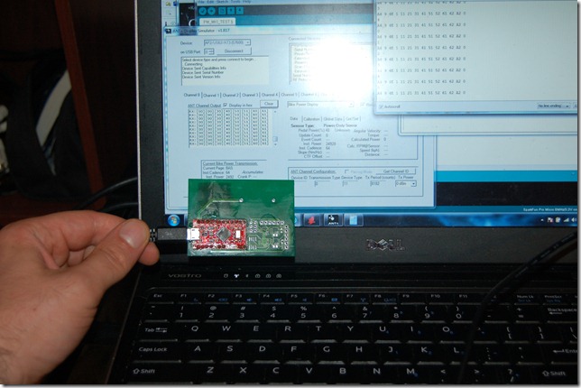
So I just ordered up a HC-06 Module for about 10 Dollars CAD and I’m going to try and wire it into my Sparkfun ANT+ stick. The stick is set to 9600 Baud already and is very simple to wire up so I figure I’ll give it a try. I’ll test it with the AP2 module after.

I don’t believe the HC-06 is FCC certified so it’s not like I could sell this. An FCC certified board is a bit more expensive at around $30 – 40 dollars. That means this translator would be near $100 minimum once packaged with a regulator and a battery.

13

So what could you do? Well, using the basic SPP protocol an Android, iPhone, tablet, Windows, etc device could talk directly to the ANT+ protocol. Meaning that someone could easily get fitness apps talking to the holy grail… I mean the power meter! Android’s been out in the cold for a while now in the ANT+ arena, so it needs a little help.

The second letter in the name of my power meter is C, so that’s a-c-X-X-X-X-X.

Happy holidays.

Saturday, December 22, 2012

Some more notes on ADC’s

I haven’t had much luck getting the SAR’s to work as I’d like. Honestly, it’d work better in Rotor’s or Garmin’s arrangement, that is, if you are essentially running two independent power meters and one just transmits its findings to the master. That way it would effectively double my sampling rate. However, as it stands, I can’t process the data on the Arduino fast enough to average out the signals to reduce the noise enough. I’ve thought about bumping to 16 Mhz. Several people have done this, and so long as you maintain good voltage it should be fine, however it is officially below the minimum requirement of the Atmega328 or Atmega32u4 chips requirements for 16Mhz.

Monday, December 17, 2012

TSSOP 20 Breakout? Help?

I’ve been reading up on the SAR (successive approximation, eg the ADS8321) versus Delta-Sigma (eg the ADS 1247). From what I can find out the Delta-Sigma’s are slower BUT they have much better noise rejection. I’m using an averaging technique with the SAR where the Delta-Sigma may not need an averaging technique or very little.

So if anyone knows of a TSSOP 20 breakout to DIP or DIL that’s available in Canada without a fortune in shipping let me know.

This could also reduce cost. The ADS1247 is approximately $13.50 CAD which eliminates two ADS8321 and AD623 and high precision resistors. I believe that is about $45 dollars. Major electronics could be < 40 dollars. Obviously, a power meter won’t be that – labour + other parts + casing + testing + overhead and equipment.

Still looking for an appropriate gyro on breakout board. I think I’ll eventually have to pick up a hot air rework station since I’m not ready to commit to a reflow oven – Gyros are only available in LGA style. If anyone in the Kitchener-Waterloo-Cambridge or Guelph area in Ontario that has one and willing to help out, let me know!

Saturday, December 15, 2012

How Many Bits is enough

Back when I was doing my Engineering Masters degree I had to build an active suspension setup, simulate it in software, and then test it in real life. That was a difficult proposition and my 300+ page thesis took 4 months to review instead of the 3 weeks costing me about a thousand dollars in tuition. However, I was using about 6 MCP3201’s tied to a Spartan FPGA that was running at about 50000 samples per second and then averaged down to 512 sample/second with an artificial 16 bits created by summing and averaging the 12 bits. Suffice to say, this did actually help when it came to differentiating the positions for velocities, but it was honestly a mess.
I’ve done some experimenting in order to determine why I can’t get stable numbers with it sitting on a table while I simulate high RPM (120 RPM +/- 40). 60 – 90 RPM seem acceptably stable at 0 watts, but at 200 RPM it could erroneously read high, up to 26 watts I’ve seen. 26 watts error is flat out unacceptable!
So I’m back to basics. Read out the samples as fast as the fake serial port can allow and I come up with a few graphs. So what I am doing is summing up so many samples and then dividing them by the count, so averaging out over so many samples. This will be referred to as Samples/Report.
image
At 2000 samples/report things look very good! Less than 1 bit of appreciable noise getting though this crude filtering technique. But things quickly go bleak.
image
At 200 samples/report we have about 3 LSB of noise almost. My 16bit ADC is now barely a 13 bit ADC.
image
At 20 samples / report things just get very very very bad. We are at 4 – 5 LSB of noise! This means I’m down to MCP3201 territory with 11-12 bit.
This wouldn’t be so bad, but with so much time spent doing floating point math, at 160 RPM the code is struggling to make 200 samples before it has to update the calculations. This is skewed because I’m slowing it down a lot by sending data over USB. However it’s much slower than I can actually read out. Keep in mind that this is reading two sets of data.
So what is the problem? It’s now ratiometric so it should be more tolerant of voltage fluctuations. I’ve tested to see if I am causing any spikes in voltage due to magnets passing over it, that’s proven to not be a problem. I think it’s one of two things, the voltage regulator isn’t great causing some additional noise, or a higher quality ADC with more bits is needed.
Let’s look at one of the other problems mentioned, time calculating versus time reading. I’ve had the serial output tell me the running time before the zeroL and before and after zeroR. This is seen below.
Speed Time (Absolute)
Start Zero L Zero R
4mhz 8017 8914 9699
2mhz 8019 9037 9943
1mhz 8017 9277 10424
Well this seems peculiar, as the time only seems marginally affected by the SPI bus speed… also, the ADS8321 should not be run at higher than 2 Mhz, but seemed to function at 4 Mhz. I won’t do it again in case of damage, but it survived and I haven’t seen any anomalies.
Speed Time (relative) Time Reading  Time Calculating
Zero L Zero R Zero L Zero R
4mhz 897 785 121 776 664
2mhz 1018 906 242 776 664
1mhz 1260 1147 484 776 663
Interesting!!!
At 2 Mhz I’m spending 3 times as long to calculate as I am to read! So what is my code! Below is the zero command. I am summing to a “Long” from a short and then after 20000 reads it averages it out.
short zeroadcL()
{
   long adcl = 0;  //initialize a long variable
   for (int i=0; i < 20000; i++){adcl += long(readadcL());}
//     Serial.print(adcl);
//     Serial.print(",");
//     Serial.println(i);} //Read 1000 times
   return (short((adcl/20000))); //Output the average
}


I think this is a limitation of two things 8 bit and 8 Mhz microcontrollers. However, it puts me back on another issue; I need the microcontroller to spend more time sleeping. If I have to bump to 16Mhz on an 8 bit AVR type chip then I might as well hold off until I can move to the nRF51 which is 32bit and shouldn’t require so many commands to sum.


A lot to think about.

Saturday, December 8, 2012

Sorry for the Lack of Updates

I’d like to apologize for the lack of updates lately. I’ve been exceedingly busy at my day job. Long days testing has slowed the development of V3.

So where is it? The short is that V3 contains some bugs. I last had some zeroing issues which I believe is sorted by replacing the LM4140 with a voltage divider but it becomes hard to test this in conjunction with the magnetic pickup code. This is the major slowdown.

As a result I very much dislike the magnetic pickup. The code will need to be edited and trimmed I suspect. My research into gyro’s indicate they consume about 400 microamps. This isn’t much compared to the current consumption, but still adds to the target.

I’m actively exploring the nRF51422 and sorting out getting either an evaluation kit or development kit into Canada. After some back and forth NuHorizons seems that they thought they originally collected Canadian tax… however they do not. This means that a 99 dollar development kit costs 99 + 25 dollars shipping + either 19.45 or more likely 29.00 to process the customs and 13 dollars taxes totalling 166 dollars, or pay the 66 dollars for express shipping totalling 179 dollars as customs brokerage is included.

Symmetry Electronics seem a little more reasonable as the Fedex Express options are only 44 dollars and include brokerage processing, but it still totals 157 dollars for a 100 dollar dev kit.

While I had earlier mistaken that Digikey carries Nordic things they do carry Dynastream modules using the nRF24AP2. The difference is Digikey is express shipping for 8 dollars, or free ver 200 dollars and no brokerage! That would mean if they did sell Nordic products then it’s total cost would be 121 dollars shipped next day.

In terms of development costs 166 vs 157 vs 179 vs 121 shouldn’t be significant, however considering all the costs up until this point I’m about 2000 – 3000 dollars into development costs depending on if you include certain elements that I use (FR60 watch kit, Garmin Edge 500, programmers, tariff processing, etc). Keep that in mind if you think this is the cheap way out to getting a working power meter. (I could have bought 2 Quarqs or an SRM) That being said I’ve been pushing my budget for this project and there are huge limitations to the way it’s built right now.

The nRF51 would allow me to drive down the board / electronics costs. The AP2 Module is very expensive (25 dollars in low volume) compared with the cheap nRF51 ($2.63) and the AP2 module still requires a micro controller. Thought a finalized arduino style board is expensive, using an atmel atmega 32u4 is about $6.50. So even if I was to drop the pre-made board, the nRF51 still comes in cheaper by a significant margin.

Oh, and one more think nRF51422 (ANT+) is interchangeable with nRF51822 which means BTLE is possible without a significant change over in board design – in fact no change over! It’ll require different code (if BTLE ever pulls together a power meter profile).

To do:

Get V3 working well enough to make some videos of it working and post the board + code

Get nRF51 development equipment.

Tuesday, November 20, 2012

Hacking your own PCB

I mentioned a problem with the LM4140 reference voltage as a poor design decision. Adding a capacitor didn’t solve it nor did adding a resistor. Realizing I was unhappy with this I decided to hack the board and put on a voltage divider for the reference voltage.

I explained before but the short is you need a voltage reference in between the +ve voltage and the ground in order to have a single sided amplifier. This reference raises the differential voltage from the strain gauge.

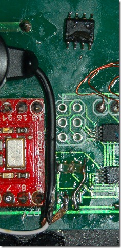
I’ve attached a picture of the old reference resistor and the hack of two resistors and a bridge wire. It’s giving much better stability.

So why is this ultra precise high grade IC failing… because it’s source is a poor linear regulator on the Arduino Pro Micro. So this means that as the supply voltage drifts up and down that means that relative the reference it’s drifting. This is now ratiometric and even if the supply drifts the reference is still at the same “relative” voltage keeping it all nice and stable.

I seriously hate magnetic reed sensors. I dislike how I have to program the microcontroller. V4 will have a MEMs gyro.

DSC_8999

I spent yesterday figuring out how would I program the nRF51422 if I switched to that for development. Kicking myself for missing out on the free board Nordic offered, but even more so for not getting the free day of training. That could be invaluable. However, my self learning has revealed that the nRF51422 is not as scary too deal with. Segger J-Link to 9 pin “JTAG” (not true JTAG as I understand it for the nRF51422 which actually uses a two pin arrangement to program, but it does contain the normal JTAG lines) is all there is to it.

A big issue with this is that if I don’t incorporate an OEM J-LINK means others can’t reprogram it. Mixed feelings on this. Let me know your thoughts? I haven’t decided if V4 will be a minor increment or more major. Feel free to let me know your thoughts via email.

Monday, November 19, 2012

So close!

After a significant amount of work I'm close to being able to show V3 working on a bike. However there are ramifications to my intention to post the code / schematics / pcb. The problem is that the pcb is continually showing faults in the design that should be addressed.

1) I forgot a trace to the AP2, so it's manually grounded

2) I have a broken trace when I had to fix some traces to get the board made. I forgot to connect this one and it has had to be hacked.

3) the precision voltage reference was the worse idea I've had for this entire project. In fact I'm going to hack my own PCB to install two Vishay through hole resistors to sort this horrid deficiency out.

4) Shear gauges on the right arm are not nearly as accurate as double bending arrangement. This should be something of note for anyone interested in StageOne. It hasn't been talked about but if they are using a surface shear gauge you could be introducing some inaccuracy. It works, but the double bending arrangement IS more accurate. This is a thumbs up to Rotor who are using a double bending arrangement inside their crank.

5) Linear voltage regulator sucks power. It's a waste and requires 2 x CR2032 to power the meter with higher drain. Not good. Connecting the 3V coin cell directly with a voltage divider reference is smarter.

6)Size: This is all too large and ridiculous in size.

7) Coin holder: It's terrible

8) Reset / On-Off Switch: Need them

9) ADC / Amp / Gauge should be powered  by an output pin so they can be turned off.

10) nRF51422. This is such an appealing device. The size of an AP2 chip but with a 32bit ARM core. Dual SPI, built in ANT+. But I have 0 true experience with ARM Cortex-M0. So little that I don't even know the equivalent of an ISP and how to even wire the chip to be programmed after assembly.

I'm working on buying a site for the commercial side of this project. So I'm not releasing the name however here is a teaser. A-X-X-X-X-X-X. Maybe I'll release one letter per post!

Wednesday, November 14, 2012

Power Meters - Why

I love bikes. I love riding. I love the feeling of the first ride of the year after being cooped up inside all winter knowing that I’m stronger, faster, fitter, healthier. I even love that feeling as I transition to indoor training where I design my workouts.

In the workout I relish that interval where I have to hold myself back because I know I can push harder. I can waver a few percentage above or below but being under is a sin. It just motivates me to push harder and harder until I am king of the world.

My target heart rates could stay the same as I get fitter and achieving that BPM might be affected by heat, humidity, and elevation but one thing doesn’t change with those factors. My Power. It’s my Power, it’s nobody else's. It’s that one measure, that one thing, that when you improve you know it. I’ve read papers that show little “statistical” difference between HRM and Power meter for short term training, but that’s not why I’m here. I need to know that I’m better than yesterday. And not just yesterday – last week, last month, last year, last race, last training ride. Only power can.

Power is new. It's expensive, but it doesn't have to be. I'm showing it won’t be. My meter is showing the true cost. Why? Because I want power to be in reach of the weekend warrior. I want that return on investment to be the feeling of more power. I want to see these on road and mountain bikes from the factory and not as an expensive upgrade for the rich and elite. That warrior is a pro in his heart so why can’t that person have the pro tools? Maybe you need the basics, maybe you need L/R measure, maybe you need pedal stroke analysis.

You feel great because you know you are better than yesterday, and it didn’t break the bank to get you those metrics. You’re an amateur weekend warrior or a pro, but either way you want to know you’re stronger. You spent all winter making sure that you’re pedal stroke is as smooth an efficient as possible, that your left and right legs are balanced, that your power is greater than last spring.

ANT+ was there first, and will always be the true power meter standard. It was forged by countless unthanked people who toiled to create that standard so that I can use a Garmin Edge with a Quarq, a Joule with an SRM, a Bontrager Node with a Powertap. It was and is being improved by companies willing to not keep that work secret, working to incorporate pedal stroke analysis in the new Power Meter Profile and who knows what else.

That weekend warrior who’s racing has the right to feel like a pro who sprints for the finish and spread their arms as they pass the line. Can you feel it? ANT+ did. I do. Click here and let me know if you feel that way.

Tuesday, November 13, 2012

V3–Update and Naming

Sorry it has been a little while since I’ve updated this. So everyone knows I’m very much committed to this project however I’m constantly running up against minor issues.
Recently I found out that I missed a 0.1 uF cap on the voltage reference causing it to drift and as a result there was a massive loss of resolution but it was hard to detect when you average 10000 samples. Also I’ve come to a realization that commercial units sample WAY WAY WAY less which is why they only claim 1 – 2 % accuracy. Strain gauges are good for way higher accuracy but it’s this combined with inaccuracy of rotational measurement and trying to keep consumption down that drives inaccuracy. So it’s a trade off, a real balancing act.
The latest issue I’m still debugging is that on V3 when I read the ADC’s the AP2 module is not consistent with transmitting. Essentially my serial output is turning to garbage. As a result it’s not transmitting consistently. I’m having a hard time debugging this and that is what I’m working on now.
I’ve gotten several emails over the last couple of weeks. I know right now that some of them have gotten lost in the inbox. I’m going to get to finding and replying. I apologize for this. Unfortunately my day job, exercise, and this project are all competing for attention.
Once this problem is sorted an updated schematic, gerber files and part list will be posted along with some basic code. It will by no means be the end of the project.
Back to debugging!

Also V4+ will have a new name, a more official name.

Sunday, November 4, 2012

Minor Improvements–V2 helps V3 Debug

DSC_8997

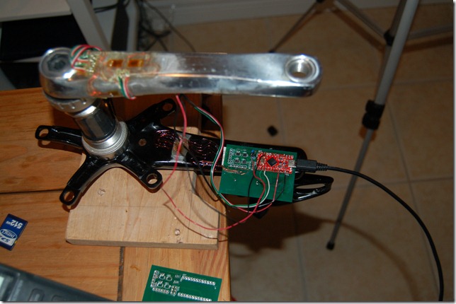
Why is the Left crank arm of V2 connected to V3 via frankenwiring? I was experiencing some very peculiar ADC behaviour. It’s hard to see, but next to the LM-4140 reference is now a blue capacitor. Turns out it was drifting very very high and erratically so that as the load changed so did the output. I missed the 0.1uF capacitor that was supposed have been after the regulator. I’ll need to recalibrate it but things are now a bit more stable. I’ve been asked about releasing PCB schematics. I’m not decided on this but this is a good reason not, to at least not yet. I also hold that without training installing strain gauges is a recipe for disaster and wasted money.

Power consumption is still an issue and with the drifting reference voltage solved, I was able to rewrite my “readadcR” routine to the “wiggle” version. My naming conventions aren’t all that sane when testing (I’m “wiggling” on and off a random pin). However interrupting the transfer to switch a pin didn’t impact the overall readout. According to the datasheet it shouldn’t but until it’s tested I believe nothing.

short readadcR() {
digitalWrite(slaveSelectPinR,LOW); // take the SS pin low to select the chip:
byte one = SPI.transfer(0xFF); // send in the address and value via SPI:
byte two = SPI.transfer(0xFF);
byte three = SPI.transfer(0xFF);
digitalWrite(slaveSelectPinR,HIGH); // take the SS pin high to de-select the chip:
return (one << 14 | two << 6 | three >> 2); //output the value from the three bytes as one short
}

short readadcRwiggle() {
digitalWrite(slaveSelectPinR,LOW); // take the SS pin low to select the chip:
digitalWrite(wiggle,HIGH);
byte one = SPI.transfer(0xFF); // send in the address and value via SPI:
digitalWrite(wiggle,LOW);
byte two = SPI.transfer(0xFF);
byte three = SPI.transfer(0xFF);
digitalWrite(slaveSelectPinR,HIGH); // take the SS pin high to de-select the chip:
return (one << 14 | two << 6 | three >> 2); //output the value from the three bytes as one short
}


image


Running the two routines (one reads and averages 10 values then the next routine does the same)yielded the above graph. Very little difference. The difference between the two techniques is highlighted below.


image


It’s obvious that at times the readings are slightly different, but this is on a 65000 value scale and averaged out the difference was 0.38 bits. Pretty insignificant as this should just be the last few bits plus a little offset for reading 10 values then reading 10 other values causing some error as I dynamically load the device.


What does this mean. Earlier here, I showed that currently I’m at 34ma, 17 - 19ma is the bridge itself! That is much too high! I’m targeting a lower value and V4 might not be perfect but it needs to be in the single digits at least. So assuming that reading the ADC takes 3/4 of the time and calculations take 1/4, and there are 3 read periods and only 1 bridge needs to be active for 1/3 of the reading that means that 19ma *1 bridge/2bridges * 1/4 duty cycle = 2.37ma.


Okay, so we dropped 19 to 2.37ma but we can still do better. If I added a minor delay to reduce read cycles in half  (8000/s per side totalling 16000 samples/s) we drop both the bridge and the ADC’s to 1.185 and the adc to 0.4ma. This should in turn put the microcontroller to sleep for effectively half the time, dropping it from 17 to 8. I suspect this is wrong due to the regulator drawing more power.


So current consumption would be at about 10.5ma so far for V4. that should give about 20 – 22 hours of operation. A far cry from Quarq’s 300 hours. I suspect that they must reduce read rates even further leading me to question how much more accurate these devices could be if they scarified operating time. Original Quarq Saturn is listed at 400 hours on a 600mah battery. Total consumption when in operation is just over 1 ma. This is brutally low as I’m still not dealing with the ANT+ current consumption, however that is very very low.

Sunday, October 28, 2012

V3–Testing Video

Yes, it’s finally getting near the point where I can put this version on a bike and not have to fight with soldering, wires, and tape to hold it together. Anyone who has seen my videos for V2 will remember that.

Slowly but surely, it’s developing

Thursday, October 25, 2012

A brief interlude

This won’t be a trip to the lobby but rather a reflection on the state of sports sensors. If you don’t want to read all of this the short is this: How come we don’t use a Bluetooth SPP and connect it directly to an AP2 module to build an ANT+ to Bluetooth bridge. It’d cost about 60+ dollars and your phone can talk to ANT+ without modifications.
Currently I have to say that as for interoperable sensors go I think Ant+ is the first time I’ve ever seen anything do better than this xkcd comic about standards. I think the biggest fiasco of it I seen was when NVidia decided to create MXM, a laptop graphics card. They built the standard, opened it to everyone, had ATI (at the time) review it and they gave them back revisions! And then what happened… Well several things happened but suffice to say it didn’t really catch on.
I think that with companies like Look and Polar being very against Ant+ they have made a decision to limit their own market share. At at least that’s how I want to see it, but it’s not the whole truth.
Look wants to go to Bluetooth LE for their KEO power meter, but there is no power meter profile and currently there is already interoperability issues for heart rate monitors using Bluetooth (but I haven’t seen it first hand) that I’ve heard of. Update: DCrainmaker has noted decent interoperability recently with the new LE devices.
Originally I picked up a Garmin FR60 so I could get a heart rate monitor and a ANT+ usb stick cheap. Each device on their own was 50 dollars, but I got the FR60, the stick, the HRM, and the foot pod shipped for 165. For and additional 50 dollars I purchased the bike sensor. This was all to gear up to make my “virtual coach” software which, while poorly written and buggy, I’ve used for the last year. When it became apparent that other people where doing the same and realizing my limited coding ability I decided to revive my strain gauge work and develop this power meter.
This is where things fall apart in terms of standards compatibility. ANT+ is great, but it’s not in phones, tablets, laptops, etc. What is common in these happens to be Bluetooth – we can thank all those hilarious looking people walking around with Bluetooth earpieces and the advent of AD2P for high quality audio in cars.
However, more and more people want to use their phones. I argued against running with my “free” phone, because out of contract it’s a minimum of 600 dollars to replace. That's right, most decent smart phones are 600+ dollars if not on a contract! My laptop didn’t cost that much! However, as I’ve gained faith in my Samsung product I’ve ditched my iPod Nano and now run with the phone. I still think my argument for getting a sensor based watch or GPS watch is valid - durability, price, weight, etc. Even the highest end models are not 600 dollars and are way more robust then a fragile smartphone. Plus my FR60 lasted a year on a single coin cell.
However, whenever I’ve met with anyone about these things the first question is usually revolving around can it be connected to their cell phone. The short answer is “likely not”.
If you have an old iPhone you could buy an adapter, now you have to buy and adapter to plug into another adapter and I haven’t heard for certain if it will work (ANT+ to 30pin, 30pin to lighting). On the Android front it’s worse as the 30 pin apple connector had serial lines, but Android has micro-usb leaving the only option to use some sort of Android IOIO device.
There exists a Bluetooth profile called SPP, or serial port protocol. The AP2 can be hardwired to serial at a specific baud rate. I’m probably going to order one of these and see if I can bridge the AP2 to Bluetooth via serial port protocol. It means that you can have this device on you, or on your bike, or in your bike phone mount.
What’s the downside. Power consumption. This is my nemesis most recently, as it’s an important aspect for the consumer market but many compromises have to be made to achieve it. Bluetooth 2.0 has the SPP profile but LE does not. That means it’s a bit more power hungry. Unfortunately I don’t know how hungry, but it’s worth the 20-30 dollars to get a Bluetooth SPP modem to find out.

Monday, October 22, 2012

V3–Power Consumption

The total power consumption doing a read to Serial over USB is approximately 35ma. This is much too high. That means a coin cell (CR2032 at 225mah) setup will likely only last 5-10 hours.
Lets take a look at the breakdown.
Current (ma)
Item 3.3V 2.5V
Bridge 9.428571 7.142857
Instrumentation Amp 0.55 0.55
ADC 0.792 0.6
Sum x2 21.54114 16.58571
Measured 35 -
Goal (100 hours) 2.25 2.25
I’m constantly looking at the bridge and thinking I must be calculating V/R wrong because I was expecting the bridge to be a much lower current draw. I'm debating if I could potentially run the bridge from a digital out. That way I can activate the bridge, take a sample, then power down the bridge. Essentially it would have a very very short duty cycle of maybe 5%. This would drop the bridge consumption to approximately .5ma per bridge from the current near 10. I hadn’t wanted to think about it at this point, but maybe I should consider that for V4 now.
I haven’t even looked at the microcontroller current consumption and optimization yet. I’ve been debating my choice of microcontroller, but it’s hard to know what is marketing and what is actually achievable. However I've been debating eliminating the regulator. Rather than using a reference voltage I could go back to my old voltage divider design and then everything is ratio metric. As the battery voltage drops so does the reference voltage. This would simplify things potentially. Switch to the Atmega 328 or the nRF51422 which is my preferred goal.

Update:

Looks like the measured does line up with consumption. I removed the bridge connections and consumption dropped to 15 - 17 ma. This is still quite high, but this is no optimization and running the ADC and Instrumentation Amp at full tilt. So the bridge is pulling similar power as everything else.

Sunday, October 21, 2012

V3–A little too sensitive?

Coming soon, current consumption measurements!

image

Above is the raw data from the calibration test. I used the setup below with a few weights from my dumbbell that weight approximately 10lbs. Here’s is how it breaks down. As you may realize that the sensors max out at a relatively low load – It’d probably be fine for testing or a 140lbs climber, but not an expected maximum. I have another resistor to set a lower gain, so I might be able to adjust this easily.

What should the maximum per pedal load be. Let’s take a worse case scenario of a 1800 watt sprinter. We’ll assume 172.5mm crank arms and 90rpm.

P = T * w = 1800 = T* (90/60 *2*pi) => T = 191 N-m

T = Lever arm * force => force = T/L = 191/0.1725 = 1107 N = 112kg

Surprisingly my max load with margin is approximately this! However we’d have to account for the downstroke being stronger than the upstroke, so the best way to do this is assume one leg is doing all the work. So in short, I need to reduce my gain to about 125 from 250 approximately. Although I might use different gains as swapping the differential pins for the Right should give me back some sensitivity.

  Left Right
Zero (bit) -13273.2 -5097.73
Loaded (bit) -17315.5 -7141.56
Unloaded (bit) -13286.1 -5104.38
Difference (bit) -4042.31 -2043.82
Load(N) 44.59091 44.59091
Torque (172.5mm) 7.691932 7.691932
Bits/N-m -525.526 -265.71
Max Torque (with margin) 83.80372 96.60148
Load (kg) 49.5228 57.08548

So I realized a couple of things. Switching the polarity of the supply and ground on the strain gauge also flips the direction it changes when loaded, so I need to swap the signal outputs for the right sensor as it goes negative when positively loaded. The problem is I was hoping to use more of the ADC range by using a lower ref voltage (e.g: –10000 to +32765, instead of 0 to 32765 which allows me to use a higher gain and thus add accuracy). I don’t know why I didn’t realize this in the last post. I’ll look at this fix tomorrow or Tuesday.

I’ve left it running for approximately an hour and it’s holding steady at –13273 +/-4 and –5097 +/3.

DSC_8994

A little two sided tape holds the board on nicely two the back of the crank arm. Should nicely clear the crank ring too!

DSC_8993

Tuesday, October 16, 2012

V3–Reading Sensors, Transmitting Power Data

DSC_8989

If you are good at reading between the lines you’ll understand that the title alludes to two separate tasks, but they have not been combined.

So the short is, the AP2 module, after a lot of fighting, is talking to the microcontroller. I was concerned when I couldn’t get the AP2 Module surface mount soldered (with only a soldering iron). It was very discouraging but I eventually solved it. This was already mentioned, and a dummy program was loaded up to transmit meaningless data on the basic power profile. See below.

DSC_8986

So the next thing was soldering on all the MSOP and SOIC components which turned out to be very easy by comparison. I guess I’m getting good at soldering tiny components by hand. So I loaded up my dummy program that reads the raw sensor data from the ADS8321 16 Bit ADC. It works fine and at a gain of 250 (using 2.5 dollar 0805 resistors instead of 15 dollar through hole resistors) gives great sensitivity.

This is going to be a bit technical but bare with me; the ADS8321 is a differential ADC so it gives –32768 to +32765. My instrumentation amp, the AD623, is a single supply differential instrumentation amp, so a reference voltage is used to raise the voltage. So we could have +/- 4mv differential, for example, but once amplified it could be +/- 1v. Since we have a single supply this needs to be raised as we can only go from 0 to +vcc. Imagine we have a 2v supply voltage, we would want to lift the 0mv differential after amplification to 1v so that we have a full range for the +/- 4mv swing corresponding to +/- 1v after the amp. This gives a range of –1v corresponding to –32768 and +1v to 32765 all from the original input of +/-4mv.

I’m using a 3.3V regulator to provide the supply voltage, but I only really care about one direction of the force so what I was expecting was the voltage to always go in one direction. HOWEVER, a strain gauge has a tolerance so you might have an offset electrically. This is more of a problem because if you don’t use a reference voltage to raise the level sufficient and it’s hanging out at –1mv and you are only reading positive voltages, you have a dead sensor area and then a massive offset when it kicks in. So it still needs to be raised, but not necessarily by the whole range. In my case I’m raising it 1.024v with the LM4140 precision reference voltages.

If you are still there this all culminates in one of my bridges has the supply and ground swapped as it’s going in the reduced range direction when I apply a force that wouldn’t freewheel the bike.DSC_8990

The next steps are mounting the PCB more securely and switching to coin cells. I currently have concerns regarding coin cells as my drain might be too high in which case I would switch to my Li-ion cells I have already. Power Management will be a very important part of development from here on out. Power reduction hasn’t been at the top of the list and I still wish to change to the nRF51422 Soc when the evaluation kits become available.

Once I can get a handle on the current consumption I’ll post the results.

Friday, October 5, 2012

V3 Progress

No pictures today. Just a bit of a text update.

I've received all the components to complete the V3 circuit board. Surface mount soldering by hand is generally difficult, but the AP2 modules are proving to be the absolute most stubborn pieces to solder that I've had the displeasure of attempting. This is a situation where you need to accept the old adage: "The right tool for the job". I am not using the right tool.

If you attempt to surface mount the AP2 module by hand here is something to keep in mind. There are small through holes for the contacts on the base, just big enough for a fine leg of a resistor to fit down. They also make great test points. If you test and cannot get the solder on your PCB to connect to the AP2 then put a wire down the hole tinned lightly with solder. Heat the wire and keep pushing it down, then alternate heating the pad on your board (the small amount exposed) and the wire while applying pressure downward. Eventually you'll make a connection. Check it with a multimeter. Once you've made a good connection heat the pad and then the wire and put the wire out -- it will pull solder up through the hole and seems to make a very reliable connection.

This is time consuming. I spent about 3 hours trying to surface mount two of these to my PCB and several connections would not connect. This technique takes several minutes per contact, so about an hour to get all the connections working. All of this could have been avoided if I had a reflow oven. Necessity is the mother of invention.

Monday, October 1, 2012

V3 New Circuit Boards

DSC_8981

As you can see above the new circuit boards have arrived from Alberta Printed Circuit Boards. These guys have some of the quickest turn around I’ve seen – you do pay for it though. I’ve designed this board to not deviate too much from the smaller circuit boards I initially built – mainly to speed development of the V3.

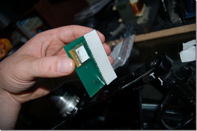
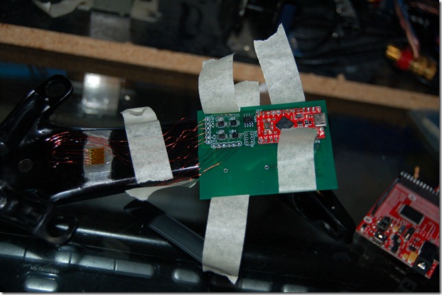
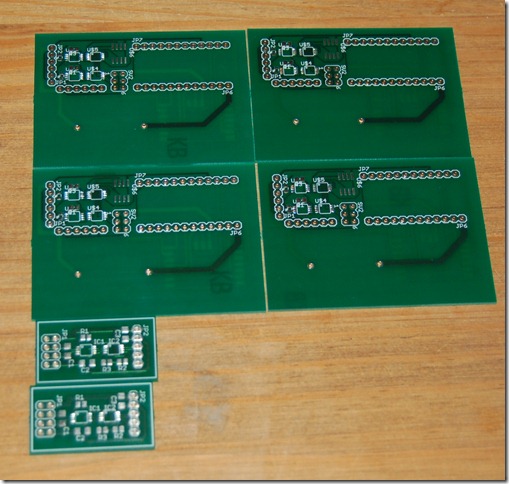
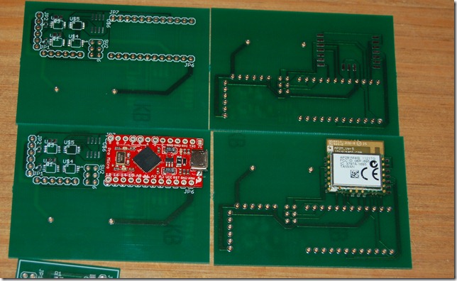
A previous post showed a circuit board with an atmega32u4 chip and the associated circuits to support it. Considering I do not have a reflow over I opted for the simpler approach of only supporting the analog and wireless on this PCB and leaving the regulator and micro-controller on an Arduino pro micro. You can see how I broke out the ISP to make it more convenient to program.

DSC_8982

Both of the boards mount to this main one – one via pins and the other via surface mount. I haven’t, but I should, incorporate power planes but I consciously did not include them as the AP2 module suggests not having anything metal under the F-Antenna. I probably took this to the extreme but after the difficulties with V2 maintaining a good signal I felt this was a good choice. The analog components are very very low power, on the order of micro-amps of current draw at 3.3v and I never had issues with the little circuit boards so I’m comfortable.

The voltage divider used on V2 is replaced with a precision voltage reference, the LM4140.

This will go on a bike without too much problem but having seen the size of the “Stages” power meter I’m keen to drive the size down. This would have been a great time to know some electronic engineer who works at any of the mobile phone companies as they can pack some power into a small space.

I’m keen to use the AP2 module as the nRF51422 hasn’t become available yet. I unfortunately missed my opportunity to get a free one as I had to renew my passport (Expired on the 25th of Sept, and the Boston conference was on the 24th). So I couldn’t book tickets or sign up for the tour, and as a result I’m waiting for nuhorizons to get in the evaluation kit.

I just submitted my order for parts with Digikey just then, so maybe a new prototype by the end of the week, but likely next week some time.

Wednesday, September 19, 2012

V3 Development–Board Design

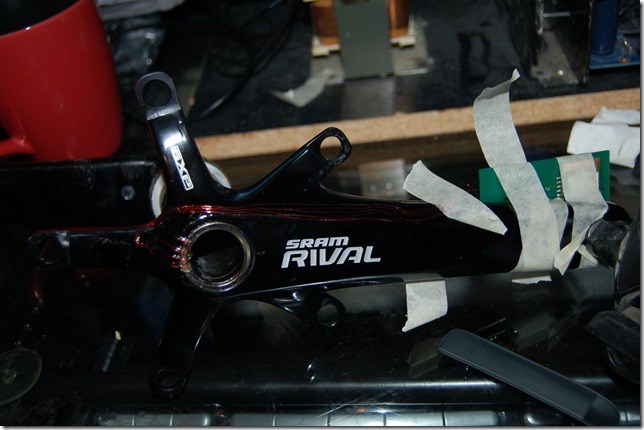
The most challenging part to the design and development of a power meter is certainly the packaging – or maybe it’s the programming, either way it’s actually not the instrumentation side of things. I think I’ve found a way to package the electronics out of the way and not interfere with the RF signal which was an issue with V2. I’m planning to move to the nRF51422 eventually but until then I’m using a hobbyist microcontroller board to speed development. The new board is to be mounted to the inside of the the chain ring side crank arm. The AP2 module will hang off behind the arm. This means there is no metal near the module to interfere with the signal. I still need to incorporate the battery. I might take the Rotor route and use the higher capacity cell rather than the 2032. Perhaps the 2477 cell.

The unrouted trace is a ground, there are multiple grounds and I’m avoiding ground loops.

image

Tuesday, September 11, 2012

V2 Working Video


This video is just meant to show my V2 prototype working. There is several bugs in the firmware so far, rotatably it doesn't reset the accumulated torque reading if it hasn't made a revolution in a while. This leads to the period timer overflowing, causing a miscalculation on the first revolution, but subsequent revolutions are calculated correctly.

It needs work -- that's why I'm building V3. The hope is that I'll have compact reliable electronics that I can continue to develop the firmware for. If you're keen you'll notice a lot of failed Rx on the laptop. Antenna placement is critical and placing it inside that torque tube is a terrible idea.

Sunday, September 9, 2012

V2 Torque Testing


Unfortunately I've been sick since Friday and I wanted to get more done this weekend than I did. This evening I felt good enough to record some short testing of the V3 and show a little of V2. Enjoy.


Friday, September 7, 2012

V3 Power Meter–Initial Instrumentation

DSC_8933
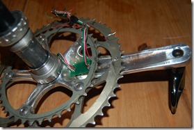
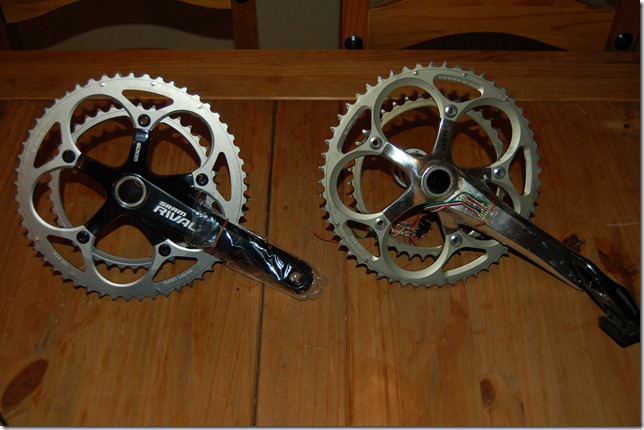
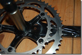
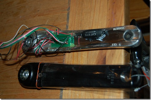
Earlier this week my new crank arrived ready to instrument. The above picture is the new crank with V2 Power Meter (currently disassembled). The new OCT hollow cranks have a flat back instead of the grooved out backing of the old pre-OCT model. This is exactly what I was expecting for two reasons.
DSC_8934DSC_8935
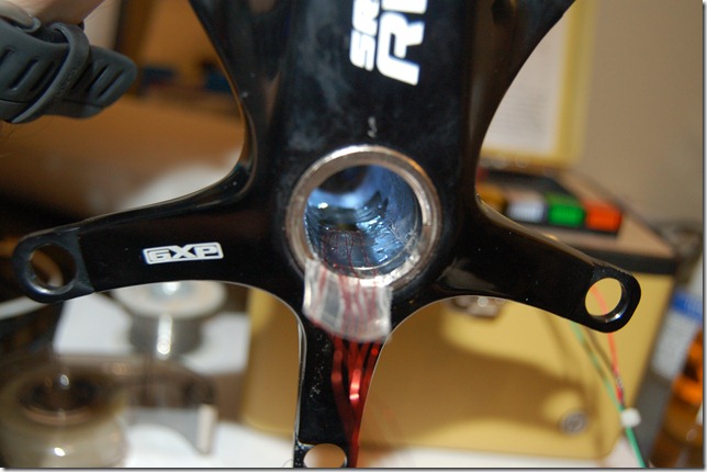
The first reason being is that the flat back is easy to mount to. Secondly, and more importantly, if a shear gauge is used to measure the drive side arm it can be placed on the inside and is thus protected. Another view is of the non-drive side arm shown below.  In V3 the non-drive side arm will not be instrumented. The torque tube that goes through the bottom bracket is instrumented instead. No wires to be run through the crank, or like Vector or Rotor, both sides do no require batteries, a master and a slave connection and the associated issues.
DSC_8938
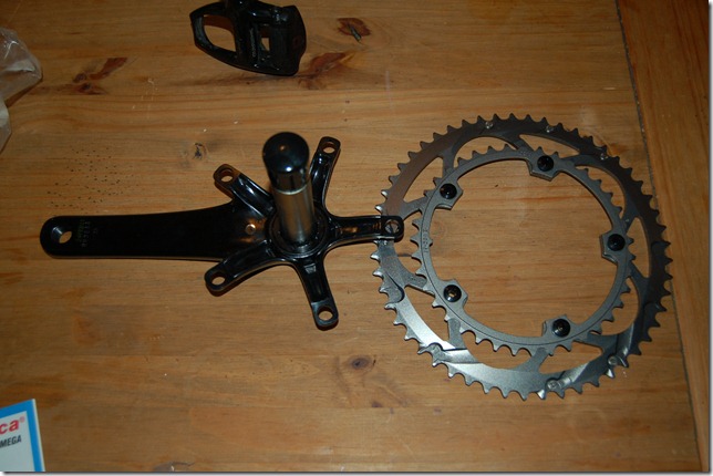
The first thing is to remove the chain rings as they get in the way. I didn’t do this on the previous builds. The loctite on the chain rings tend to make them very difficult to start backing off. I was getting some very large flex in my Allen keys. Two socket drivers work best, or a socket driver on the small side and an Allen key on the other.
DSC_8936
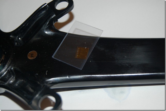
On that singular polymide backing is 4 strain grids. There has been some confusion caused by power meter manufacturers. A gauge is the grid(s) on a polymide backing. In this cause this is one strain gauge that has four sensing grids. However for marketing purposes this would be referred to as four strain gauges. I could use single grid gauges but that is an inherently flawed design that is more time consuming. It’s primary flaw is that each grid could be aligned poorly, there is a greater propensity for a bad glueline, harder to mask the areas, etc.
DSC_8939
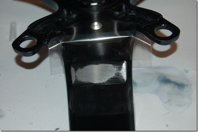
I used masking tape to mask off the area but when using Vishay Conditioner and sanding with 180, then 320, then 600 grit paper destroyed it very quickly. I masked the area with PCT-2M tape instead and continued sanding. This or their MGJ mylar tape works best for masking.
DSC_8942
After sanding with conditioner, flood the area, wipe with gauze, then flood with neutralizer and scrub with cotton applicators (Q-tip with wooden stick) until no more metal residue comes up. Flood with neutralizer again and then wipe away with clean gauze – do not reuse, wipe in one direction only, and don’t wipe with anything that contacted your sink. Those oils can ruin the glueline.
After cleaning a piece of glass or plastic with neutralizer, place the gauge down and use the PCT-2M tape as shown to pick it up. Remove the tape and gauge with by peeling back at a shallow angle.
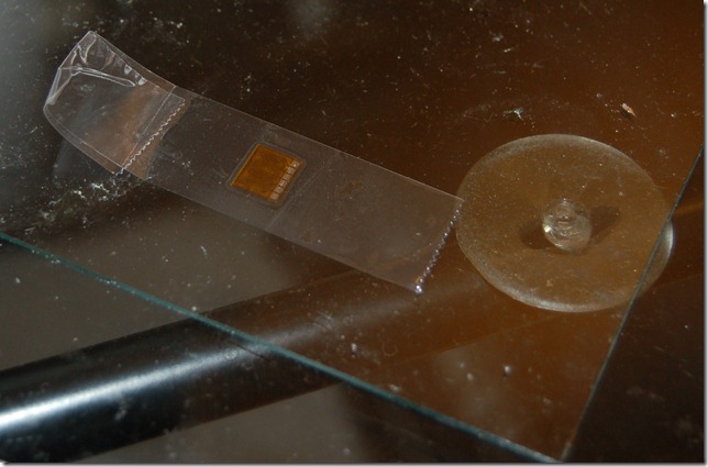
DSC_8944
Apply to the prescribed area. Peel the tape back, again, at a shallow angle, apply accelerator, wait for it to dry, then apply glue to the surface just before the gauge and wipe the gauge down with gauze from back to front, then apply finger pressure. The APP Note from Vishay best describes this and it requires some practice to get right.
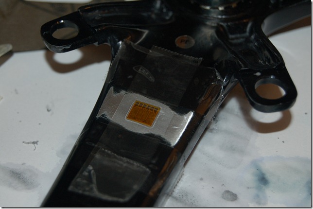
DSC_8945
While waiting for this to dry onto the hard part. The gauge in the hole. The gauge needs to be laid on a clean metal surface because the wires will need to be soldered to it. Cover the gauge except the contacts with PCT-2M tape.
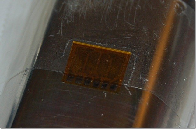
DSC_8949
Now, painstakingly apply flux, tin the contacts, tin the fine magnet wire, and solder on the wires. It’ll start looking like the picture below after using solvent to remove the tape ever so carefully.
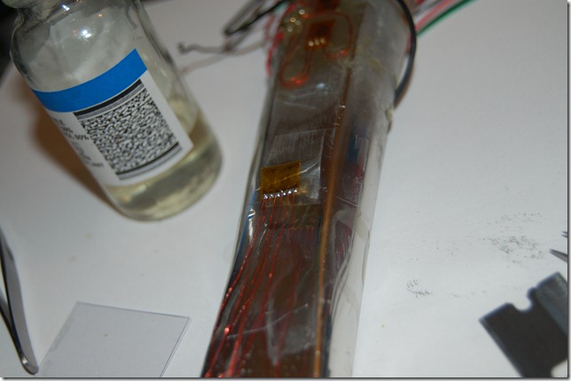
DSC_8950
Place the gauge in a clean bottle of solvent to remove any flux or residue.
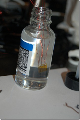
DSC_8951
The next steps were impossible to really photograph, but I did manage to get me applying pressure to the gauge while it’s in the hole.
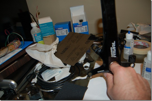
DSC_8954
It’s hard to see but the gauge is in there.
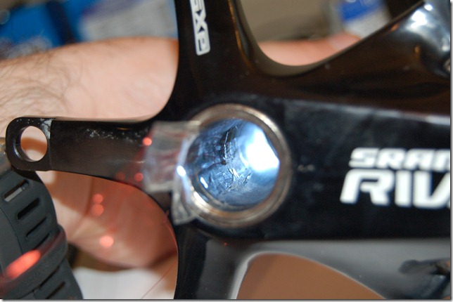
DSC_8961
Using the M-Coat A, the inside gauge is coated and let to set.
DSC_8965DSC_8964
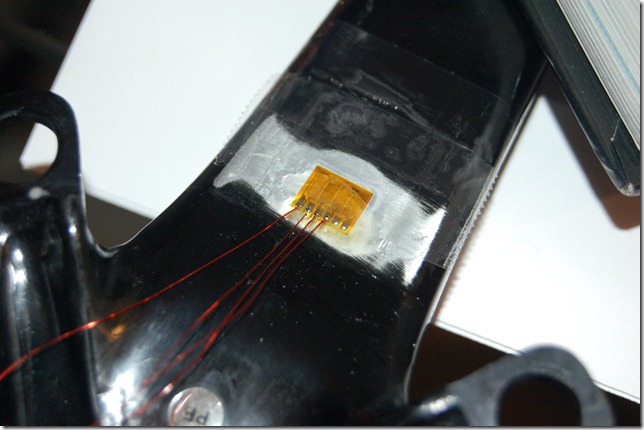
Below is how the soldering looks on the arm. This is then flooded with solvent, let dry, and then coated with M-Coat A. The gauges have their resistance checked by a Vishay Gauge Installation tester 1300. These pricey little old school looking boxes are high quality resistance measurement units. They can also measure in the Gohm range for resistance to ground and do this with 10VDC which is safe for almost all gauges.
DSC_8974
More updates coming soon. I have a National Instruments Compact DAQ this weekend that I will be testing the installation sensitivity with.