Tuesday, May 28, 2013

Kicad–Schematic 90%–PCB 15%

image

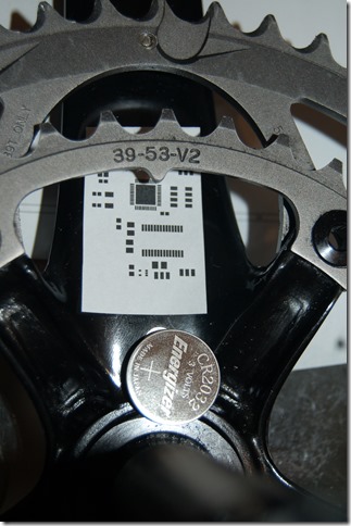
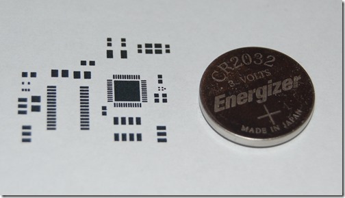
Some slow progress, but it’s coming along. The schematic is about 90% done, but the PCB has barely been touched. I’ve just been doing some trials making sure it all translates well in Kicad from schematic to PCB layout. Below you can see the footprint layout compared to a CR2032. This is quite small. The trace PCB antenna will come off from the integrated balun from ST micro to the right. You can see the peculiar five dot layout next to the nRF51422 QFN footprint. This is ST micros integrated Balun. It’s 2mm^2.

DSC_9226

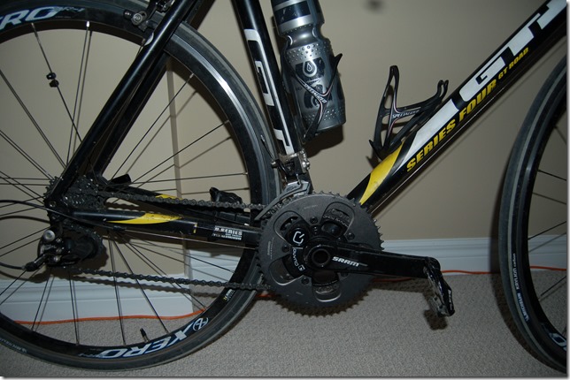
To give you an idea on where this is going to reside I have added the picture below. The area just behind / below the chainrings seems sufficient for the circuit board. However two major hurdles.

  1. Battery Placement
  2. Antenna Placement

Coin Cell for scale. Note: I’m showing a CR2032, but I plan to use a CR2450 620mah cell. Slightly bigger physically.

DSC_9228

Once I get the schematic and board close to finalization I will order the parts from Digikey. Most of the parts are very inexpensive except the ADS1248. This is considered the heart to the design in my mind.

When I order strain gauges I’ll also be ordering platinum RTDs. Each RTD will sense one of 3 strain gauge locations. (Top and Bottom for Right leg sensor, one for left leg sensing).

This is going to be close to a “NEVER ZERO” power meter. Rotor is pretty much there from what I’ve heard, but mine will be priced much more competitively once out of the beta. FTSH header include for reprogramming / hacking via the CMSIS-DAP.

Hoping to have the rough PCB by the end of the weekend, and a 3D concept of the enclosure which will be 3D printed. The enclosure will likely just resemble a circular battery holder by the crank arm and a simple covering over the board and strain gauges. Nothing fancy.

Tuesday, May 21, 2013

5.07ma–Almost Coin Cell Ready, Death of Gyro

Phew. It’s taken a bit, but in theory – and in individual component measurement, I am down to just about 5ma of current. On a CR2450 battery this should be almost 70 - 100 hours depending. It’s slightly out of spec for current consumption but it’s close to acceptable.

How does it break down?

image

The nRF51 is maxing out at 2ma. I’m hoping to get this a bit lower, but I’m not 100% sure it’s easily possible. After realizing I was drawing 18ma to the protoboard with the ADS1247, I realized that I wasn’t just powering the ADS1247, I was actually powering a nRF24AP2 Module. After sorting it all out, I measured the ADS1248 which is what I’ll be using and it fell in around 0.62ma, rounded up to 0.65ma.

Putting a resistor in series such that the voltage drop is around 0.5v across the Wheatstone bridge which gives a current of 1.21ma measured. This was about 20 counts of noise on the 16bit, until I placed a capacitor across the bridge (the Voltage input, not the output) and it stabilized it back to the 0/1 counts I was experiencing already. I’m hoping I can push this even lower, possibly 0.3 - 0.5ma per bridge. That would get me down to 3.5ma. This is seemingly safe coin cell operation area for the CR2450 and I think reasonable.

So, there hasn’t been much mention of the gyro. It’s likely out for now. Sorry. I’m making provisions for future testing. Essentially I’m putting in the ability to add a recharge circuit, rechargeable lithium battery input, and the gyro in the circuit board. However, they won’t be included in initial prototypes.

There are gains to accuracy to be had by using the gyro, but in terms of cost and development time, I am making the executive decision to aim for coin cell operation and thus a magnetic switch. 1.0% to 2.0% accuracy is achievable over the pedal stroke, it’s just when you get into high rates (every 45 or 90 degrees for instance) that there would be loose in accuracy.

I’m after low cost implementation with some advanced feature sets. In order to get to the minimum viable product I’ve had to make this decision. Otherwise it’d be September / October before I could have prototypes ready with a gyro.

In other news, I’ve been informed that the programmers that I wish to include with the beta’s are currently having circuit boards built. This is good news as it’ll only be a few weeks before I can test them out.

Wednesday, May 15, 2013

PCB or Enclosure–Chicken and the Egg

After spending 3 hours literally looking at bike cranks, holding them in very different ways, in different light, cutting out pieces of cardboard and tucking them in different places I can honestly say I have no idea which to work on first – the PCB or the enclosure. I think that the design of both items has to happen concurrently, each iteration causing the other to update until they converge. So I’m moving forward concurrently as best as I can.

The sad thing is that where I want to instrument, and where I can place electronics / battery / antenna are two very different things. Luckily I’m down to about a 5 component setup (battery, nRF51422, Balun, hall sensor/gyro, ADS1248). The bulk of these things are small and I can fit all of them except the battery into a space about 2 – 3 square centimetres. The battery, that’s still another story as it’s not fully decided. It needs more power measurement work.

While I want to keep both the pcb and enclosure as universal as possible, so that I can instrument various different cranks without too much work, I’m going to have to choose one to start with. SRAM Rival. Why? I already have 4 unused ones that have been purchased. BSA / 68mm threaded, are the most common BB’s and compatible with things like BB90 and BB30 via adapters (though I’ve heard mixed feelings on these, some good, some horrendous). I’ve also noticed a lot of BB30 cranks are three piece cranks now, or that the shaft is now on the non-drive side arm. This complicates things a bit for me. It’s not impossible, it’s just annoying. Learning from my Trek Madone about BB90, I have to say that I’m warming up to BBright and BB386. 30mm spindle is great, but wider BB is better in my mind for stiffness – and more importantly for me installation strain gauges inside

Where the problem is in designing something that doesn’t interfere with the legs motion. In picking up a used Quarq unit I noticed shoe scuff marks in what I thought was the most impossible place. My shoe has never rubbed my crank while cycling, but I’ve seen the result and it certainly happens. I don’t know why, if it’s acceptable or if it’s something that should be corrected in their cycling gait, but they are there. If my electronics package sticks out anywhere it could get caught. It would be pretty lame business practice to not thing about this before building.

Other issues such as the chain. If it comes off the big ring due to an over shift then I need to keep the electronics out of the way, or baring that, make them small and durable enough that it isn’t an issue. The first is preferred.

I’m back from a ride and looking at a SRAM Rival, S950, and S975 Quarq Saturn Cinqo and still lacking ideas.

As for my Trek Madone, it is now together (though with a temporary rear derailleur cable stop) and feels so different from my aluminum frame. The wheelbase is shorter so its more responsive, but honestly the big change is in stiffness and damping. It feels smoother with the crank, and I feel less vibrations over rough roads. Being a heavier guy, I have longingly wanted a stiffer bike, tapered headset, and wider BB. It feels so much nicer but I keep wondering what bikes like that are like in the hands of people who are much more capable riders than myself. I need to adjust the setup and I only have a temporary magnet setup for the Quarq with sticky tape, so I’ll have to fix that if I want to keep gathering background data to compare in the future.

Sunday, May 12, 2013

nRF51422 Power Meter Dev Video

Quick Video showing the basics working. It’s not truly calculating power yet, but that is a minor calculation. I’m mainly debugging and trying to figure out power consumption right now.

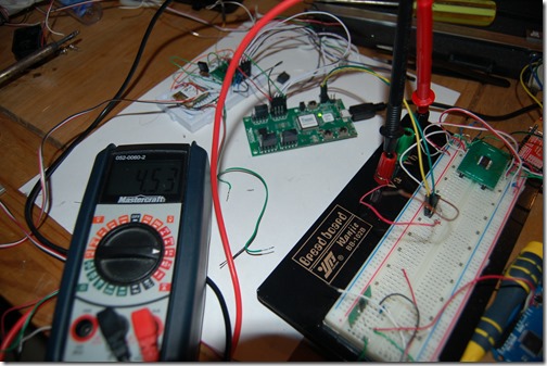
Current Measurement

DSC_9218

Minor coding changes can have a major effect on current consumption. The above was taken running a while loop to wait for the DRDY line to de-assert itself. Notice the nRF51 is using 4.53ma.

Friday, May 10, 2013

Progress Update and Commentary – With Finn and Jake

Anyone who knows me personally know that I’m a big Adventure Time fan. I love the nonsensical nature of the show as it provides a nice relaxing escape. Lately I’ve been gathering all the pieces for my Trek Madone 5.2. It’s not really a 5.2 as it is not going to be kitted out with Shimano (Ultegra) gear. It will receive my SRAM Rival group set that was purchased a few years ago and put on my GT GTR Series 4 which had originally came with Sora / ST-2200 shifters. I’ve tried to keep my bike with my ability level – however a Madone 5 Series is well beyond my need. I promise this is going somewhere. Just stick with me after the break.

Commentary

While I’ve trained with what I’ll call “Virtual Power”, which is using the regression curves for my Kurt Kinetic for 3 winters now, I haven’t experienced outdoor power until now. It is a very different experience having those numbers in front of you on a road. It’s teaching me it’s hard to zone in on a specific number and stay there. For my weight (100kg, I’m a big, dense boy) I’ve found that if I don’t push 400-500 watts then I don’t really go up even the smallest of hills very quickly. I recently read in the Wattage group that you really need a year of playing before you can seriously use this data. I’d say I’m not a novice, but I am not intermediate with data.

Having used this “Virtual Power” for a few years I thought I would be decent at evaluating power meters and what makes them good or bad. I’m a much more technical person, and as such I consistently forget that the coaches and athletes who use these tools while not knowing really how they work really. They don’t understand what would make one better than the other, which is why most people blindly say one is better than the other without understanding the technical merits of one over the other.

I’m not making any evaluations on products here, but I’ve been reading quietly in a lot of forums. In a previous post I showed how strain gauges, even in thermally compensated designs, can drift – very repeatedly drift as a function of temperature. A “good” auto-zero algorithm would adjust the zero based on this temperature – the holy grail, the platinum standard, etc, of power meters which wouldn’t require the user to do so much interacting. I don’t know the algorithms used by Powertap, SRM, Quarq, Rotor Power, etc but I do know that I am incorporating an auto zero adjustment because it will make it more accurate.

Rounding full circle to how I began, I will soon have a bike of very high level equipped with a tool that I think should be bought long before other bike upgrades but most people won’t get a power meter until they have a 4000 dollar bike. I am in no way capable of fully utilizing the performance of such a high quality frame. I’m nervous about this frame but not for the reasons you would expect. I’m nervous because showing off my prototype on it may illicit feelings that this is going to be another 2000 dollar plus product.

My goal in trying to create a lower cost power meter is to allow those aluminum framed, entry level, Shimano 105 / SRAM Apex/Rival / Campy Athena people who want to train more effectively to do so. It’s the 1500 – 2500 dollar bike people. The people who’s bike is equivalent to the price of one of these training tools currently. I think I will keep my 2008 GT GTR frame such that when I show off the new prototypes I can show them working on both my old used aluminum frame and my new carbon bike.

Progress Update
image

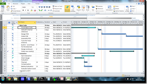
Seriously, I want to give a huge shout out to the people who made Arduino possible. What they did was translate the cryptic language of microcontrollers to something more easily digestible and along the way made some simple tools. I’ve been stuck for two plus weeks on “Basic Code”. I’ve been stressed out because it’s been improbably annoying to replicate the millis() function of the Arduino which is necessary for calculating cadence from any pulse type sensor. It had to do with existing “Timer.c” library that came in the reference code. It was quite annoying.

This has throw off the schedule somewhat, however I believe I have it sorted finally. However, in sorting this out I found out that the reference code doesn’t work like I thought it did and is therefore less power efficient than I thought. This comes as a surprise, though I am seriously behind on a couple of tasks. The Gyro Evaluation still shows up and I still want to do it, but it’s hard to make it happen. The priority now is the current measurements. I have to get this done this weekend now that the cadence calculation is almost worked out. At least I’m 3 weeks ahead on ordering cranks.

I really wanted to be doing PCB design this week which is why I took three days off work – such that I could do more work. Who knows, I might get to start on it yet.

Monday, May 6, 2013

Parts Are Arriving

DSC_9202

Prototype parts are starting to show up. The first items are the cranks. Currently the line up include 4 x SRAM Rival GXP 53/39 172.5mm, 1 x S950 50/34 170mm. I’ll likely be picking up a few more in the coming weeks. I want to get a shorter 165mm arm unit as I want to explore the unwanted force rejection characteristics of a shorter arm.

DSC_9203

I’ve also received a used Quarq S975 (50/34 172.5mm). However, in putting it on my bike I had to lower my front derailleur hanger. That was fine, however, I find that for my cadence and the local roads have me switching between small ring and big ring a lot. With a full size crank I was either in the small ring or the large ring more consistently (53 for flats, 39 for climbs). I might look for a 52/36 110bcd chain ring setup, but then I have to send it in for calibration. The S950 (or maybe the existing crank arm) will be instrumented for a double-power meter. This will likely be the unit I send to Ray over at DCrainmaker.com.

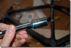
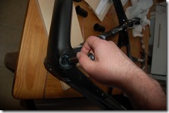
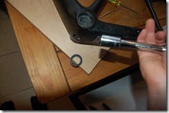
I picked up a used Trek Madone 5.2 frame, but it was setup for Shimano cranks. I therefore had to remove the bearings. They aren’t “pressed” in tight, so the non drive side came out easily but the drive side did not want to. An 11/16th socket made a good bearing removal tool as you can see below.

DSC_9210DSC_9211DSC_9212

Sadly it came with a 130mm seat cap, which comes up 10 – 20mm shy of what I need to match my setup on the GT GTR bike seen above. I need to source a 175mm cap version now. Hopefully a Trek dealer in area or near Toronto has one.

Programming is going slowly. I haven’t looked at it in a week, so I’ve been stuck at 80% complete. The App Timer for measuring cadence with a magnet sensor is the only thing I haven’t sorted. I was really caught up with the force rejection and thermal testing and I wanted it sorted as best as I could. I’m still not 100% satisfied but I am generally settled on the strain gauge and temperature sensor design.

As for the gyro / battery debate I’m just making a call and sticking with it until I get out a minimum viable product for people to test. I am thinking on designing the circuit board to support both though. That way switching down the road is more about a new rapid prototyped enclosure than a major redesign.

I’m also in talks with a couple of companies to supply me with programmers for the prototypes. These boards I am designing use a two wire interface for reprogramming the nRF51422 chips. In order to field update firmware these would have to be included with the prototypes (or built into them which I do not wish to do).

What I’ve heard most is that people would like their devices to update more to get more accurate data. ANT+ is every 0.25 seconds but it will only update the page information that is transmitted once a rotation. This is where the gyro can come in. It can give much faster, and therefore more accurate information. Like I said I am likely going to include the gyro, but not enable it initially. I’m aiming for coin cell but will include a charging circuit for Lithium that can be disabled. These are low cost to front load and doesn’t take up much physical space.

I’m taking three days off the day job to recover and work on the circuit board design.

Thursday, May 2, 2013

Testing Results

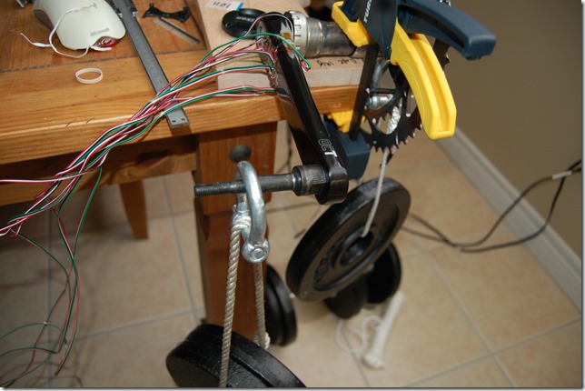
I have written a couple of partial posts and have chosen against posting them. Upon re-reading I was feeling that I haven’t added any real content – just subjective opinions on technical things. In the background I’ve been doing a lot of testing.

DSC_9207

What have I been testing then:

  • Calibration accuracy
  • Sensitivity to forces that don’t contribute to actual power generation, referred to as anomalous force rejection.
  • Thermal sensitivity
  • Quarq Power Meter – To be written up later

More after the break.