Monday, July 29, 2013

Status on V4.1 Accuity, Crowd Funding Comments

DSC_9446

I wanted to give a quick update as I’m going to be away from this project for about 1 – 2 weeks. In the meantime I started a discussion on crowd funding over at slowtwitch here. Feel free to swing over and leave a comment, or drop me a line (here) as an alternative or in the comments below. I want to know peoples issues, concerns, hopes, etc. Do they see a market? is price the major issue? Is the app scene pushing adoption? Would you use a power meter if it was cheaper? Anything else?

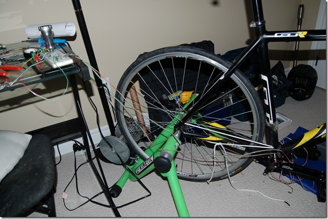
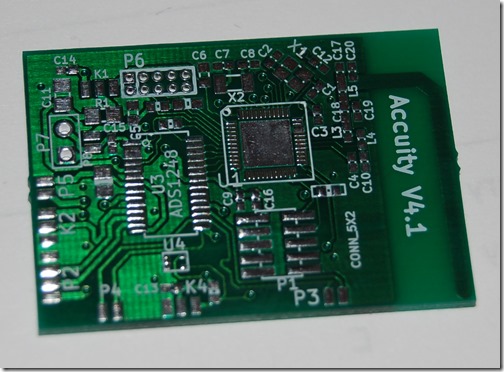
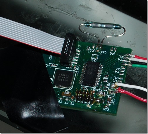
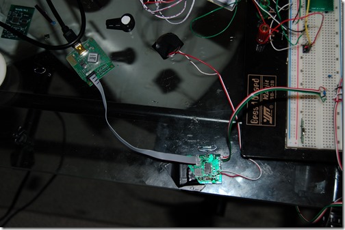
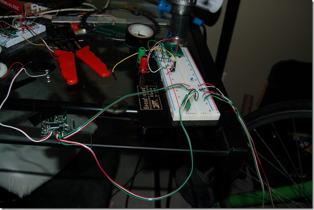
I was hoping to get the board on the crank set and bring it with me so I could continue coding and sorting out bugs but that proved improbable. From the above photograph You can see my custom board connected to a breadboard. This is just a quick way of changing setups during testing. The board is wired to a coin cell battery that I’ve actually been using for a couple of weeks. Even after shorting it out a few times I still haven’t had to replace it. Still reads about 2.9V. Bodes well for long operation. I’m aiming for a minimum of 100 hours, hoping for 150 – 200 hours with some optimization.

DSC_9447

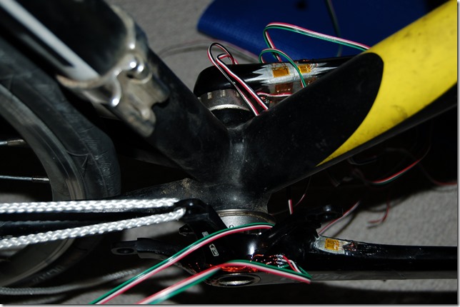
From the breadboard the inputs are wired to my former V3 power meter. V3 was “sacrificed” so I wouldn’t waste a crank (makes for an additional prototype as well) and it serves as a quicker test setup than building a new one from scratch. The interesting thing Is I have a a total of 5 different ways to measure the left legs torque, and 1 way of measuring the right leg. This is great for torque testing and confirming the shear gauge measurements against other designs. I’m well past this stage, but more confirmation results certainly help the process.

DSC_9445

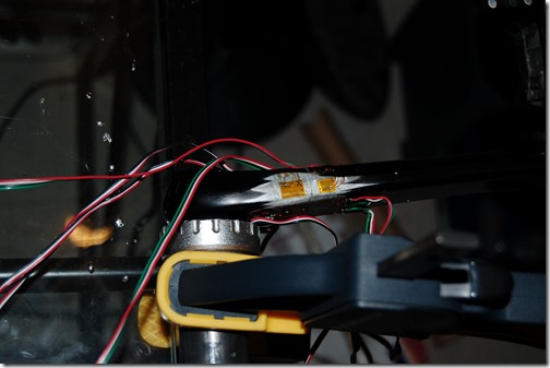
Just a close up shot showing off how I’ve modified V3. The setups now connect to bondable terminals for stranded wire connections. The board will migrate onto the crank arm by the chaining and these wires will be shortened.

Look for further updates in about 2 weeks. Feel free to email me in the meantime.
Wednesday, July 24, 2013

Launching a “Product”

image

Some people have remarked that they may have either been confused about the goals of the project. This is the result of these goals being fairly fluid. Shown above are the next three major phases left in this project. First is to finish building the latest prototype (70%+ Complete) which will serve as the template for the beta units. Once this is debugged I will be producing several Beta units. Initially I’ll loan them out locally, then I will loan them via mail to other candidates. Assuming that things go well I am going to take a serious look at using Kickstarter as a launch platform for development kits and potentially a final FCC / ANT+ approved version. Development kits would be targeted for Delivery in Jan / Feb 2014 while a finalized version would likely be Spring of 2014.

More details of each phase after the break.

Sunday, July 21, 2013

Single Sided Measurement, Kickstater Coming to Canada

DSC_9429

Just a reminder, the above board made by APCircuits has worked out well. They are a 7/7 mil service however the board was designed for 6/6 mil process of OSHpark. The problem was the turn around. APCircuits had the order on a Wednesday night and it was delivered Monday afternoon. Total cost is $88 dollars shipped with Fedex Priority which was $30 for 4 boards. OSHpark is 17 shipped for 6 boards.

APCircuits are very good, they reminded me that there were “errors” in the board, but as previously mentioned I told them to go ahead. I haven’t found a single problem with the boards and I’ve tested all the small traces. I have tested the RTD sensor lines but they are larger to decrease resistance so I’m not concerned.

DSC_9434

Above is the board connected to the debugger, battery and a single full bridge setup which is connected to my 4 setup test arm used in thermal testing from here. This means it’s pretty much equivalent to the Stages One powermeter. Single sided, but that’s just for testing out, coding and debugging.

Below are a few more pictures.

DSC_9438DSC_9440

I expect that I’m going to have to re-adjust timelines. I’m away beginning of next month for a wedding and waiting until I’m back to order the strain gauges needed. I’m going to look into re-adjusting my proposed schedule and see what I can do. The “to do” list is still extensive but nothing impossible. The hardest thing really was the reflow. While still not perfect it’s fine. Again, the solution was to ditch the BGA package. That’s advice for any hobbyist with a DIY reflow oven. BGA is too much of a headache, QFN is hard but not impossible. Still haven’t received any import bill for mouser yet.

  1. Finish coding that couldn’t proceed until the boards were completed and working
    • I only coded initially for one side
    • I’m cheating and only outputting raw reads to the power, this is mainly for debugging
    • Sort out UART connection to help “debug”
    • Look at implementing TE/PS measurements – This is low priority as no head units can read it
    • I won’t code thermal until later and I get a sample RTD from omega
  2. Enclosure design – I decided to hold back a bit on this due to adjustments that might need to be made for the board design.
  3. Instrument another crank (or V3 to conserve cranks, have to rework it by removing old gauges and installing the new ones in the right locations (slight movement and different gauges)) and connect up powermeter.
  4. Mount battery, measure current consumption.

My rate of work on this has to slow down anyway from both a financial position and a time position. The board was the main hurdle at this point, right now getting it together. However I am seriously looking at Kickstarter when it comes to Canada in order to offer the Board (~$40), Dev units ($500 – 600), and final units on Hollow Forged Cranks ($700 FCC Approved). At least that’s the goal. I’ll know more when I get circuit board manufacturing quotes and find out minimum order quantities in a few weeks.

Tuesday, July 16, 2013

ACCUITY V4.1 WORKS (Sans ADS1248)

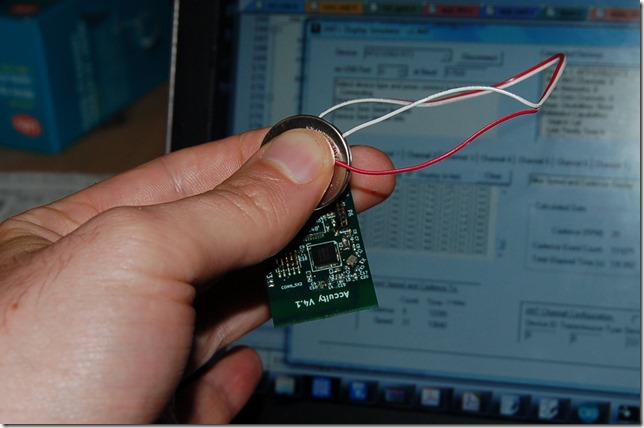
Transmitting below, hard to make it out but it’s receiving.

DSC_9432

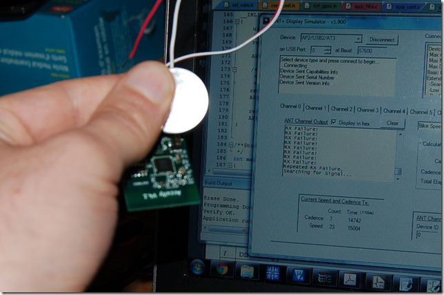
Let go and voila, not receiving!

DSC_9433

On break for a day or two.

Monday, July 15, 2013

New boards from AP circuits, SRM takes pot shots at Garmin

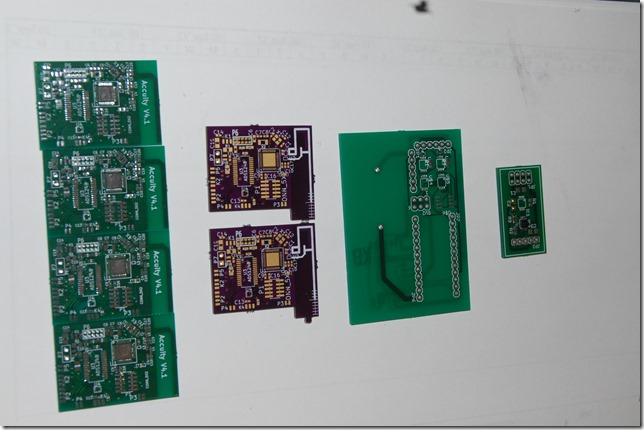
DSC_9427
From left to right: V4.1, V4, V3, V3 circuit boards.
I like the purple ones best but they just don’t have the turn around time of APC.
In other news SRM seems to be taking pot shots at Garmin / Look Keo Power.
image
“Rider contact points, like the pedal, were initially looked at for prime PowerMeter placement. After extensive testing, SRM determined the pedal option would not give the same durable performance and accurate torque measurements as the crank spider”
This isn’t Garmin’s arrangement. Garmin is using a differential bending beam arrangement with piezo strain sensors. The differential bending beam would reduce much of the error in SRM’s design which is highly sensitive to pedal offset and angle torqueing as my experiments showed for the shear gauge on the crank arm.
image
However, measuring at the crank arm seemed like they couldn’t find fault. In fact it’s written as if this is their comparison case, but didn’t like that it only measured one leg each.
“In order to accurately measure power, SRM tested torque measurements in the crank arm, against the measurements in the spider. The crank spider is the first point where pedaling forces from the left and right leg meet, before that force is transmitted to the drive train”
Seems like they don’t have anything negative to say on this type of instrumentation. That’s at least a positive for me. As it should be as this is how a professional load cell would be setup essentially.

Thursday, July 11, 2013

It’s a two pronged attack

My board was designed for OSHpark’s 6/6 mil process, however APcircuit is a 7/7 mil process. I’ve asked them to go ahead, but it voids any guarantee of functionality so I’ll have to check the boards. As a result I also uploaded it to OSHpark and chose the “free” shipping option. It’ll cost 16 dollars for 6 boards as a backup, so I’d gladly get that underway now rather than in a week if the APC boards fail.

Wednesday, July 10, 2013

Accuity V4.1

image

And so it begins. Again.

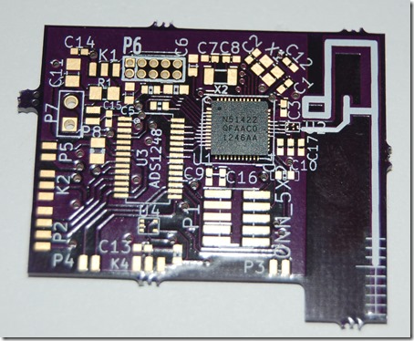
I’m going to submit it to APcircuits in Alberta today or tomorrow. Problem is the drill holes are too small. Question is do I spend hours adjusting them or can they just drill them slightly bigger, but then they might over drill and cause disconnects. You can see the ST Micro Balun removed, replaced by discreet components with a trace antenna stolen directly from the EK and DK boards. I asked in an antenna group why all trace antennas are smaller than the 2.8mm calculated width for 50 ohm. I’ve yet to get a reply.

When I order the extra parts for these boards from Digikey I’ll probably get a few more St micro Baluns to try one more time. I think I have a better process, but I’m fairly certain something is messed up. Still not 100% sure it’s not the LFCLK, but pretty close.

Don’t copy– Okay, don’t mind if I do?

image
Nordic says don’t copy or use the EK and DK schematics as a reference . They say use the specific reference schematics and layout but design the antenna yourself. I don’t like that their Balun’s are different on the reference. I might ask why.
Sorry guys, but advice not taken. I’ve seen these work, with good range. The DK and EK trace antennas look to be identically built on 1.6mm FR4 boards with the same copper weight. The DK is two layer, the EK is four layer, but the antennas and components are identical. So I’ll try it.
ST Micro offered some help because of my twitter comment. After describing my problems they (correctly) blamed my reflow setup / stencil. I didn’t suspect it was a problem with their hardware, I suspect their Balun was meant for more professional production and that everyone, even the pros, will have to waste a few of these Baluns. Just less than me.  I just bit off too many things in one step. Namely trying to make an antenna setup while trying to get the ADS1248 onboard too and figuring out how to reflow a QFN. Baby steps people!
I might be able to shrink the size of the board back as the discreet balun moves the antenna up. This is good news as an L shaped board added 4mm to one dimension. This brings it back to near SD card sized I hope. 2 boards = 30 dollars, 4 = 50 dollars, and 30 dollars shipping. APcircuits turn around is hugely fast, so that’s who I’ll be going with on this. I’ll use OSHpark when I sort out any problems.

Tuesday, July 9, 2013

Did I kill my board?

image

After getting the last of the balun’s soldered I still can’t get it to transmit. It’s getting stuck at sd_softdevice_enable. I’ve tried everything. No luck. It indicates either:

  1. The 32.768 khz crystal is not hooked (cold solder joint)
  2. The transceiver is fried

I’m inclined to think the later because I can see a good solder joint, it even wraps around the edge a bit and there is clear separation between the pins. I suspect it’s a fried transceiver because I’ve had to reflow the board so many times and I think I’ve shorted ANT1 and ANT2 to each other, to ground, to Vcc, to just about everything. I have no Balun’s left. I did however receive 10 new nRF51422 from Mouser which I suspect I’ll be getting a tariff bill in the mail from Fedex. I mean, Fedex are jerks for cross boarder tariffs but they still be UPS by a wide margin.

Which of the following do I do?

  • Design new board, order from APcircuits (1 week turn around at most). 6 boards = 100 dollars
  • Design new board, order from OSHpark (25 day to 1 month turn around). 6 boards = 50 dollars (costs more to ship than the actual boards).
  • Order new Baluns, build up last two boards. Might destroy these too but could be more careful?

It’s a hard decision. All involve even more money. I was asked today how much I’ve put into this project, and I really don’t want to think about it. I feel desperate to get this board working though. A month setback really starts pushing beta testing into next year as the ride season comes to a close.

Continually jumping off cliffs…

A friend of mine tweeted today:
“We have to continually be jumping off cliffs and developing our wings on the way down.” - Kurt Vonnegut
Since Friday (July 5th) I’ve jumped off of a lot of cliffs. About 9/10 times my “wings” didn’t work, leaving me to ask why. Okay, enough with the metaphors. On to ramblings about solder reflow and where my prototype boards are.

Saturday, July 6, 2013

Delays on Post :(

I’m trying to reflow my circuit boards I recieved. Test 1 failed, test 2 in the oven cooling after a two stage reflow attempt. More details to come, but suffice to say QFN packages suck for DIY. I always suspected this would be an issue. Lots of test reflows went great, it’s just the stencil doesn’t work for the QFN (or BGA of the Balun). As a result I’m delaying my post entitled “Launching a Product” which will outline the next stages.

Tuesday, July 2, 2013

PCBs Arrive! Also, what is a Beta test?

DSC_9377

The PCB’s arrived today. Six of them! So I have five I can ruin. I generally have good luck with PCB’s but I suspect this time I will not be so fortunate. I’ll mess up a few reflows before I get the IC’s soldered. Basically my first attempt will be just the Balun, nRF51422, and the crystals. I can sort the rest by soldering iron. It’ll be a lot of work, but I don’t want to ruin so many parts unnecessarily.

Here is something that has blown my mind. I’m basically still on track. I’ve got about 2 weeks to assemble and tune the PCB trace antenna and finish the enclosure design. . I am actually getting better estimating timelines it seems.

image

Really this is going to spill over to the build 5 – 10. Why? Well it’s simple -- I don’t have the strain gauges. I have three for the left sensor, but zero for the right (and I need 2 strain gauge rossettes for the right arm). I have lots of test beams to work with though, so continuing development won’t be a problem.

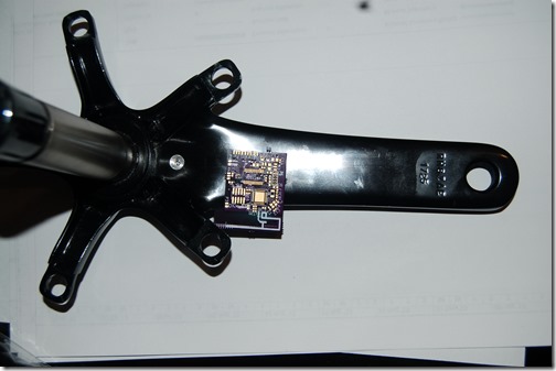
So here is a picture of where it will sit on the arm.

DSC_9371

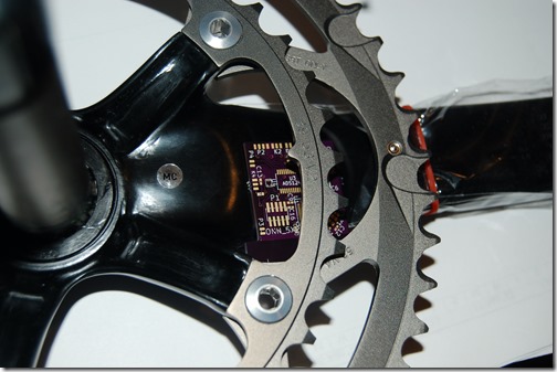
And now with chain rings.

DSC_9376

There was a comment in my previous post asking what is my goal of all this. I’m going to explain this in a few days. The question asks “as I have alluded, I am a little confused as to where you are going with your economic and sales model." While I did a basic explanation, I think it’s time to spend some time presenting my long term goals with this – including major commitment points (including financial commitments), and potential exits (and reasons why I would exit). I’m going to spend the next few days pulling this together, so keep tuned. I’m aiming at Thursday or Friday post.

Beta Tests

I understand that I’ve confused several followers on several points. Some people who emailed me about beta involvement have offered money, or hardware. I can’t stress enough that I am not accepting money or hardware for the beta. I will be loaning the hardware to beta testers and will eventually reclaim it.

To clarify first off. An alpha test is where it’s been debugged by the developers and any other people who have been directly involved with the product development. A Beta test involves people who have generally considered an end user, they may be tech savvy or early adopters, who test and are willing to accept, work around, and report bugs and issues. They work with the developer to be fix problems and ensure the product is what consumers expect.

I still have to alpha test the V4 once it’s built. This should get it ready for beta, however the beta units will have to be built up so this will take a few weeks. I’ve compiled a list of people, their bike hardware, etc and I will be working to get things ready for them in the coming months.

The circuit board and strain gauges will be enclosed and able to deal with some light weather, but no major testing (such as IPX67) will have been conducted. The people who are local can have their units installed by myself, or a local bike shop if they prefer. Any non-local beta testers will have the crank shipped to them in original SRAM (or FSA potentially for BB30 / 386) packaging. Duration or testing is expected to be about about a month. Once the test is over I’ll pay for return shipping or for local testers I’ll replace the users original cranks. I’m mainly looking for verbal feedback, but files recorded via head units could be emailed to me which will aid in my development. I’ll be following up throughout the entire test. Probably weekly at pre determined times or via email.

Simple, right?